Latest Posts

Elementary Compressible Flow – Part 1

This month’s column briefly examines compressible fluid flow.  This journey will be a short excursion into a rather complicated discipline with only two aims.  The first is to give a flavor of how and why the energy equation, which has been essentially unused in previous analyses, plays a role and how additional thermodynamic information (spatial and temporal variations in density and temperature) comes into play.  The second is to setup all the equations needed to understand the basic physics associated with that object that ushered in the space age: the rocket nozzle, which will be the subject of next month’s entry.

Following the usual introductory approaches (e.g. Eric R. Pardyjak’s online notes and Chapter 9 of Merle C. Potter’s Fluid Mechanics Demystified), we will look at only simplified geometries, such as the converging nozzle shown here

with a flow from left-to-right as indicated.

This analysis assumes that all of the flow variables are constant over each cross-section but can differ from cross-section to cross-section.  The first condition means that the flow is effectively inviscid, since the boundary layer is ignorable for the vast majority of the flow, and it is steady.  All of these simplifying assumptions result in algebraic flow equations that come from the integral forms of the fluid equations rather than the differential equations.  In addition, we will ignore body forces (i.e. gravity) and only allow pressure-driven flows.

The conservation (i.e. Eulerian) form of the equations is slightly easier to work with and these will be our starting point for the various simplifications that we impose (although with one extra wrinkle in the case of energy).  All of the derivations will involve some vector quantity (say the velocity $${\vec V}$$) being integrated over a surface after being projected onto the local surface normal.  This process results in an average value of the normal component of the vector over the entire face.  This quantity will be denoted simply as a scalar (e.g. $$V_1$$) with appropriate labeling indicating which segment of the bounding surface.

Continuity Equation

Our starting equation is

\[ \int_{{\mathcal Vol}} d {\mathcal Vol} \, \frac{\partial \rho}{\partial t} + \int_{{\mathcal S}} d {\mathcal S} \, \rho {\vec V} \cdot {\hat n} = 0 \; .\]

Since the flow is steady, the first term vanishes.  If we imagine the surface as shown in the nozzle above, then only the flow through the endcaps ($${\mathcal S}_1$$ and $${\mathcal S}_2$$) is non-zero and

\[ \int_{{\mathcal Vol}} d {\mathcal Vol} \, {\vec V} = {\rho}_1 {\hat n}_1 \cdot {\vec V}_1 A_1 + {\rho}_2 {\hat n}_2 \cdot {\vec V}_2 A_2 = 0 \; .\]

Accounting for the direction of the flow relative to the respective normals we arrive at

\[ {\rho}_1 V_1 A_1 = {\rho}_2 V_2 A_2 \equiv {\dot m} \; . \]

Momentum Equation

Next, we consider the momentum equation expressed as

\[ \int_{{\mathcal Vol}} d {\mathcal Vol} \, \frac{\partial \left(\rho {\vec V}\right)}{\partial t} + \int_{{\mathcal S}} d {\mathcal S} \, (\rho {\vec V}) {\vec V} \cdot {\hat n} = \int_{{\mathcal S}} d {\mathcal S} \, {\mathbf T} \cdot {\hat n} \; ,\]

where $${\mathbf T}$$ is the Cauchy stress tensor.  Following the same approach as above, and recalling that the body forces are zero (i.e. $${\mathbf T} = – P {\mathbf I}$$), the Cauchy momentum equation takes the form:

\[ {\rho}_1 {\vec V}_1 ( {\vec V}_1 \cdot {\hat n}_1) A_1 + {\rho}_2 {\vec V}_2 ( {\vec V}_2 \cdot {\hat n}_2) A_2 = -P_1 A_1 {\hat n}_1 – P_2 A_2 {\hat n}_2 \; .\]

Again taking into account the direction of the flow relative to the normals, we arrive at

\[ {\rho}_2 V_2 A_2 {\vec V}_2 – {\rho}_1 V_1 A_1 {\vec V}_1 = ( P_1 A_1 – P_2 A_2 ) {\hat n}_2 \; ,\]

where we’ve used $${\hat n}_1 = – {\hat n}_2$$.  Two things are worth noting about this equation.  First, the direction of the flow must be along (either parallel or anti-parallel) to the end-caps, nicely in keeping with the assumption that the flow varies only from cross-section to cross-section and not within a cross-section.  Second, the continuity equation can be used to eliminate many of the terms in favor of the constant mass flow rate $${\dot m}$$.  Keeping all this in mind brings us to the scalar equation

\[ {\dot m} (V_2 – V_1) = (P_1 A_1 – P_2 A_2) \; . \]

Energy Equation

Up to this point, we’ve not had to occasion to use the energy equation for the simple fact that in incompressible flows without explicit heat flows and generation, the internal energy of each fluid element remains constant; only the kinetic energy changed.  Indeed, the energy equation for such a flow follows immediately by taking the dot product of the Cauchy momentum equation with the velocity.  In these simple cases, the density is a given and only pressure and velocity are unknown.  The four equations of continuity and 3 components of the Cauchy momentum equation sufficed to solve for the four unknowns.

Once we allow the flow to be compressible, the density becomes an unknown and the also the internal energy enters into the picture.  The energy equation provides one more equation.  The final equation comes from a thermodynamic equation of state.  For this latter equation, we will assume the ideal gas law.  Often, it is more convenient to switch from internal energy to temperature by using the ideal gas relation

\[ e = c_v T \]

and

Fourier’s law relating heat flow to temperature via

\[ {\vec q} = – k \nabla T \; .\]

There is an additional thermodynamic consideration (the one wrinkle mentioned at the beginning of this post).  It is the introduction of the enthalpy $$h = e + P/\rho$$ that combines the internal energy with the pressure work.  Its introduction is really a matter of convenience rather than an important insight but, as the majority of the discipline’s practioners uses it, it would be a mistake to omit.

To see how the energy equation admits its inclusion, start with the energy equation in its full glory

\[ \int_{{\mathcal Vol}} d {\mathcal Vol} \, \frac{\partial}{\partial t} \left[ \rho \left(e + \frac{V^2}{2} \right) \right] + \int_{{\mathcal S}} d {\mathcal S} \, \rho \left(e + \frac{V^2}{2} \right) {\vec V} \cdot {\hat n} = \\ \int_{{\mathcal Vol}} d {\mathcal Vol} \, \rho \left( {\vec a}_{body} \cdot {\vec V} + {\dot Q} \right) + \int_{{\mathcal S}} d {\mathcal S} \, \left( {\mathbf T} \cdot {\vec V} + {\vec q} \right) \cdot {\hat n} \; .\]

By the above assumptions, the volumetric heating and the heat flow are zero, the body forces are zero, the stress tensor simply accounts for the pressure, and the flow is steady.  Under these conditions, the equation reduces to

\[ \int_{{\mathcal S}} d {\mathcal S} \, \rho \left(e + \frac{V^2}{2} \right) {\vec V} \cdot {\hat n} = – \int_{{\mathcal S}} d {\mathcal S} \, P {\vec V} \cdot {\hat n} \; .\]

Collecting terms gives

\[ \int_{{\mathcal S}} d {\mathcal S} \, \rho \left( e + \frac{P}{\rho} + \frac{V^2}{2} \right) {\vec V} \cdot {\hat n} = 0 \; , \]

or, when integrated, accounting for the normal on the endcaps, and using the definition of enthalpy

\[ \rho_2 V_2 A_2 \left( h_2 + \frac{{V_2}^2}{2} \right) – \rho_1 V_1 A_1 \left( h_1 + \frac{{V_1}^2}{2} \right)= 0 \; .\]

Summary

Finally, we can summarize all the relations

\[ \begin{array}{ll} {\textrm{continuity:}}& {\rho}_1 V_1 A_1 = {\rho}_2 V_2 A_2 \equiv {\dot m}\\{\textrm{momentum:}}& (\rho_1 V_1^2 + P_1) A_1 = (\rho_2 V_2^2 + P_2) A_2 \\{\textrm{energy:}}& h_1 + \frac{{V_1}^2}{2} = h_2 + \frac{{V_2}^2}{2} \end{array} \; , \]

which are basically the Rankine-Hugonoit jump conditions used in shock wave propagation analysis (assuming $$A_1 = A_2$$).

Next month we will apply these equations to elementary compressible fluid and the production of shocks.
Elementary Viscous Flow – Part 2

This month’s column finishes up the study of elementary viscous flow and presents the final two examples, both dealing with shear-induced flow.  This type of flow (called Couette flow) typically results from the no-slip condition in which a moving boundary drags the fluid that touches it into motion.  That layer of the fluid then drags the fluid layer next to it and so on.

For both of these examples, we are going to ignore body forces and external pressure differences and focus on the boundary motion alone.  These assumptions eliminate several terms from the incompressible Navier-Stokes equations leaving us with

\[ \frac{\partial {\vec V}}{\partial t} + ( {\vec V} \cdot \nabla) {\vec V} = \nu \nabla^2 {\vec V} \; , \]

augmented with the usual incompressibility assumption $$\nabla \cdot {\vec V} = 0 $$.

Cylindrical Couette Flow

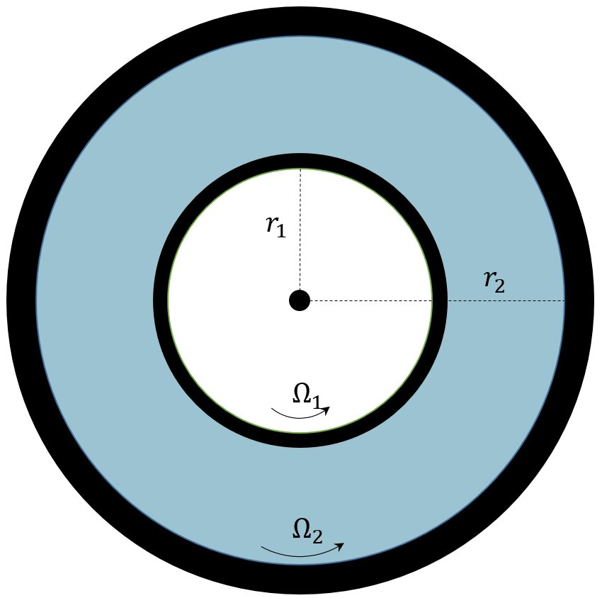
In this example, we imagine a fluid trapped between two cylindrical shells, an inner and an outer shell, of radii $$R_{inner} \equiv R_{1}$$ and $$R_{outer} \equiv R_{2}$$, respectively.

For sake of generality, both shells will be allowed to rotate about the vertical axis (out of the page) with angular velocities $$\Omega_{inner} \equiv \Omega_{1}$$ and $$\Omega_{outer} \equiv \Omega_{2}$$.  We seek to describe the velocity profile of the fluid in steady motion.  With the radii and angular velocities assumed to be known there will be a fairly simple relationship between the velocity profile and the kinematic viscosity $$\nu$$.  A viscometer uses this experimental setup to measure kinematic viscosity by tracking the torque required to keep the inner shell moving at a constant rate (the out shell is usually fixed).

The Navier-Stokes equations are best presented in cylindrical coordinates since these coordinates match the geometry involved.  The added benefit is that expressing the derivatives in cylindrical coordinates is instructive in its own right.

The key point to focus on is that in cylindrical coordinates, the basis vectors in directions perpendicular to the $$z$$-axis change as a function of azimuthal angle $$\theta$$.  The radial unit vector changes as

\[ \partial_{\theta} {\hat e}_r = {\hat e}_{\theta} \; \]

and the azimuthal unit vector as

\[ \partial_{\theta} {\hat e}_{\theta} = – {\hat e}_r \; .\]

In steady flow, by symmetry, the velocity field is a function of radius alone

\[ {\vec V} = V_{\theta}(r) {\hat e}_{\theta} \; \].

The nabla operator takes the well-known form

\[ \nabla = \frac{1}{r} \partial_{r} ( r ) + \frac{1}{r} \partial_{\theta} + \partial_z \; .\]

Under the flow geometry assumptions, the convective portion of the material derivative becomes

\[ ({\vec V} \cdot \nabla) = \frac{V_{\theta}}{r} \partial_{\theta} \; .\]

Applying this operator to the velocity field yields

\[ ({\vec V} \cdot \nabla) {\vec V} = \left( \frac{V_{\theta}}{r} \partial_{\theta}\right) (V_{\theta} {\hat e}_{\theta}) = – \frac{V_{\theta}^2}{r} {\hat e}_{r} \; \]

The Laplacian of the vector field becomes

\[ \nabla^2 {\vec V} = \left( \partial_{r}^2 + \frac{1}{r} \partial_{r} + \frac{1}{r^2} \partial_{\theta}^2 \right) ( V_{\theta} {\hat e}_{\theta} ) = \left( \partial_{r}^2 V_{\theta}+ \frac{1}{r} \partial_{r} V_{\theta} – \frac{V_{\theta}}{r^2} \right) {\hat e}_{\theta} \; . \]

The assumption of steady flow then leaves the incompressible Navier-Stokes equations, in component form, as

\[ – \frac{V_{\theta}^2}{r} = \frac{1}{\rho} \partial_{r} P \; , \]

\[ 0 = – \frac{1}{\rho r} \partial_{\theta} P + \nu \left( \partial_{r}^2 V_{\theta} + \frac{1}{r} \partial_{r} V_{\theta} – \frac{V_{\theta}}{r} \right) \; , \]

\[ 0 = – \frac{1}{\rho} \partial_{z} P \; . \]

Note that the incompressibility condition is automatically satisfied by the form of the velocity field.

From the last equation the pressure cannot be a function of $$z$$ and since everything else in the second equation is only a function of $$r$$ so must $$\partial_{\theta} P = f(r)$$.  Integrating gives

\[ P(r) = f(r) \theta + g(r) \; , \]

the form of which requires $$f(r) = 0$$ otherwise the pressure would be a multi-valued function.  The second equation now becomes

\[ 0 = \nu \left( \partial_{r}^2 V_{\theta} + \frac{1}{r} \partial_{r} V_{\theta} – \frac{V_{\theta}}{r} \right) \; , \]

The general solution is

\[ V_{\theta} = A r + \frac{B}{r} \; .\]

In the interest of brevity, the solutions for the constants are

\[ A = \frac{ \Omega_{2} r_{2}^2 – \Omega_{1} r_{1}^2 }{r_{2}^2 – r_{1}^2} \; \]

and

\[ B = \frac{ (\Omega_{2} – \Omega{1}) r_{1}^2 r_{2}^2 }{ r_{2}^2 – r_{1}^2} \; , \]

which are easily obtained by applying the boundary conditions to the general relation $$V_{\theta} = r \Omega$$.

Once $$V_{\theta}$$ is known, the first equation gives the radial pressure gradient due to the rotation.

Linear Couette Flow

In this last example, we will solve the time varying Couette flow setup up between two plates separated by a distance $$w$$ and extending far in the $$x$$- and $$z$$-directions so that we can ignore the edge effects and model the flow as two-dimensional.

We imagine that the fluid is at rest prior to $$t=0$$ at which time the upper plate is set into motion with velocity $${\vec V} = U {\hat e}_x$$.  There is a well-known steady solution in which the velocity linearly varies from zero on the lower plate to $$U$$ on the upper plate but it is interesting to see how the transient flow settles into this steady state.

By our earlier, assumptions, the flow is of the form (automatically satisfying the incompressibility condition)

\[ {\vec V} = V_x(t,y) {\hat e}_x \; , \]

which has to satisfy the following form of the Navier-Stokes equations

\[ \rho \partial_{t} V_x = \mu \partial_{y}^2 V_x \; . \]

The boundary conditions and initial condition are

\[ \textrm{BCs:} \;\;\;\;\;\;\;\; \left\{ \begin{array}{l} V_x(t,0) = 0 \\ V_x (t,w) = U \end{array} \right. \; \]

and

\[ \textrm{IC:} \;\;\;\;\;\;\;\; V_x(0,y) = 0 \;\;\;\;\; 0 \leq y \leq w \; , \]

respectively.

The solution strategy is to employ separation of variables.  To that end, following Acheson, write the velocity as a sum of the steady solution and a time-varying piece where the latter has homogeneous boundary conditions

\[ V_x(t,y) = \frac{U}{w} y + {\tilde V}_x(t,y) = \frac{U}{w} y + f(t)g(y) \; . \]

After performing the separation of variables, we arrive at

\[ \frac{1}{\nu} \frac{1}{f} \partial_{t} f = – s_{n}^2 = \frac{1}{g} \partial_{y}^2 g \; , \]

where $$s_n$$ is a separation constant.

The spatial equation, $$g^{\prime\prime} + s_{n}^2 g = 0$$ has general solutions $$g(y) = A \sin (s_n y) + B \cos (s_n y) $$.  Applying the boundary conditions requires $$B=0$$ and $$s_n = n \pi / w \;\; n = 1, 2, 3, \ldots$$.  The time equation is easily integrated to $$f(t) = \exp( -s_n\nu t )$$.  The general solution is

\[ V_x(t,y) = \frac{U}{w} y + \sum_{n=1}^{\infty} A_n \exp \left( – \frac{ n^2 \pi^2}{w^2} \nu t \right) \sin \left( \frac{n \pi}{w} y \right) \; . \]

The initial conditions are satisfied by picking the $$A_n$$ appropriately.  The key to doing this is to exploit the orthogonality

\[ \int_0^w \sin \left( \frac{m \pi}{w} y \right) \sin \left( \frac{n \pi}{w} y \right) = \frac{w}{2} \delta_{mn} \; \]

to get

\[ A_m = -\frac{2}{w} \int_0^w \frac{Uy}{w} \sin \left( \frac{m \pi}{w} y \right) dy = \frac{ 2 U (-1)^n }{n \pi} \; . \]

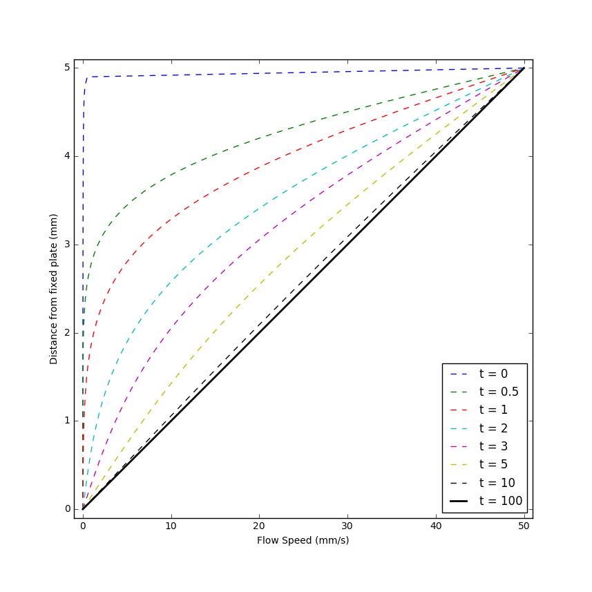
The following plot shows this solution for $$w = 5mm$$ and $$\nu = 0.8926 mm^2/s$$.

Note the majority of the velocity is confined near the top plate at short times (this is essentially the boundary layer) but how quickly the solution tends to the steady state.

As a way of seeing this boundary layer as a feature of the transient behavior consider what happens if the top plate moves in an oscillatory fashion with velocity $$U \cos (\omega t) $$.  Assuming that the fluid velocity has the form $$ V_x(t,y) = f(y) e^{i \omega t} $$, the Navier-Stokes equations yield

\[ f” – i \omega/\nu f = 0 \; .\]

Following the usual strategy $$f = exp(\lambda y)$$ gives values

\[ \lambda_{\pm} = \pm e^{i \pi/4} \sqrt{\frac{\omega}{\nu}} \; .\]

Some spirited complex algebra leads to

\[ V_x(t,y) = U e^{-ky} e^{i (\omega t – k y) } \; ,\]

where $$k = \sqrt{\omega/2 \nu}$$.  As the following animation shows, the velocity at the upper plate follows the motion of the plate but the main action is confined to a thin layer.  Essentially, the motion is always transient and the influence of the fluid motion near the moving plate isn’t able to diffuse into the bulk of the fluid.

Elementary Viscous Flow – Part 1

This month’s column deals with viscous flow in a variety of situations.  Three main physical effects can drive elementary fluid flow: the pull of gravity coaxing a fluid downhill; a pressure differential, such as in a pipe, causing the fluid to flow from inlet to outlet; or shearing motion, which, in the usual scenario, involves a moving boundary dragging the fluid.  We’ll be looking at four examples covering different aspects of these three effects.  The first two will illustrate the effect of gravitational body forces and pressure differentials to drive the fluid and will be covered in this column.  The next two examples deal with steady and unsteady shear-induced flows and will be featured next month.

But, before we deal with specific examples, we will need to settle on a model of the fluid.  Usually, when seeking analytic solutions describing the motion of non-ideal Newtonian fluids (already a simplification compared to the amazingly rich and diverse types of fluids that nature offers), one either chooses to assume the flow is viscous and incompressible or that it is inviscid and compressible.  For these examples, we will choose the former.

The starting point will be the incompressible Navier-Stokes equations, of which the flux-conservative form is

\[ \frac{\partial \rho {\vec V}}{\partial t} + \nabla \cdot (\rho {\vec V} {\vec V}) = – \nabla P + \mu \nabla^2 {\vec V} + \frac{1}{3} \mu \nabla \left( \nabla \cdot {\vec V} \right) + \rho {\vec g} \; .\]

Applying the incompressibility assumption ($$\nabla \cdot {\vec V} = 0$$) is easy to do using the Lagrangian form of the equations, but it is more instructive to play with the flux-conservative form.  Most of the action takes place on the left-hand side so let’s focus on that by expanding the terms to get

\[ \rho \frac{\partial {\vec V}}{\partial t} + {\vec V} \frac{\partial \rho}{\partial t} + {\vec V} ( {\vec V} \cdot \nabla \rho ) + \rho ({\vec V} \cdot \nabla) {\vec V} + {\vec V} \rho (\nabla \cdot {\vec V}) \; .\]

The last term vanishes under the incompressibility assumption.  The second and third terms, combined, are

\[ {\vec V} \left( \frac{\partial \rho}{\partial t} + ( {\vec V} \cdot \nabla ) \rho \right) \; .\]

The quantity in the parentheses vanishes when applying incompressibility to the continuity equation, as follows:

\[ \frac{\partial \rho}{\partial t} + ({\vec V} \cdot \nabla ) \rho + \rho \nabla \cdot {\vec V} = \frac{\partial \rho}{\partial t} + ({\vec V} \cdot \nabla ) \rho = 0 \; ,\]

where the first expression is the full continuity equation and the second is what is left after the incompressibility assumption is applied.  The left-hand side is now simply

\[\rho \left( \frac{\partial {\vec V}}{\partial t} + ({\vec V} \cdot \nabla) {\vec V} \right) \;. \]

The third term on the right-hand side vanishes due to the incompressibility assumption.  Dividing by the density gives the general form of the Navier-Stokes equations for incompressible fluid flow:

\[ \frac{\partial {\vec V}}{\partial t} + ({\vec V} \cdot \nabla) {\vec V} = – \frac{1}{\rho} \nabla P + \nu \nabla^2 {\vec V} + {\vec g} \; , \]

where $$\nu = \mu/\rho$$ is the kinematic viscosity.

This equation is what we will use in the following examples.

Gravity-driven Flow

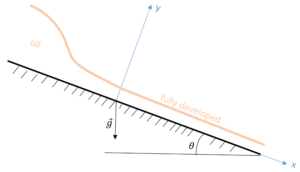
This example derives from the very nice YouTube lecture by Rick Sellens.  Here we imagine flow of a fluid, such as oil, down an inclined plane (flow in the $$x$$ direction), as shown in the figure below.  The height of the oil is larger at the top of the ramp but it quickly thins as gravity accelerates the oil.  Eventually, the viscous force equals the component of the gravitational force parallel to the plane and, thereafter, the height of the oil is constant (the flow is said to be fully developed) and the velocity profile depends only on $$y$$.  Once the flow establishes itself, this height profile remains constant in time and the flow is steady, allowing us to set all time derivatives to zero.  We will assume that the incline is wide enough in the $$z$$-direction (not pictured) that we can approximate the flow as being two-dimensional.  Next, we will confine our description to the fully developed portion of the flow ($$x > 0$$).  Finally, we will assume a no-slip boundary condition at the incline plane and, since the flow is open to the air on top and air is not particularly viscous, we will assume the shear stress on the upper surface to be zero.

Applying the steady, fully-developed, and 2-D flow assumptions leads to the continuity equation

\[ \partial_x V_x = 0 \; \]

and the $$x$$- and $$y$$-component Navier-Stokes equations of

\[ 0 = g_x + \nu \frac{\partial^2}{\partial_y^2} V_X \; \]

and

\[ 0 = -\partial_y P + \rho g_y \; ,\]

where $$g_x = g \sin(\theta) $$ and $$g_y = g \cos(\theta)$$, are the components of the gravitational acceleration parallel and perpendicular to the surface of the incline, respectively.

The continuity equation merely confirms what we already assumed, $$V_x = V_x(y)$$.  The $$y$$ component of Navier-Stokes says that the pressure at the surface of the incline is higher than at the top due to the weight of the oil above.  All the action is in the $$x$$-component equation.

Integrating the equation once yields

\[ \frac{d}{dy} V_x = – \frac{g_x}{\nu} y + C_1 \; . \]

The constant of integration is determined by the shear-stress-free boundary condition at the free surface and gives $$C_1 = g_x h/\nu$$.

Integrating the equation a second time yields

\[ V_x = \frac{g_x}{\nu} \left(h y – \frac{1}{2} y^2 \right) + C_2 \; .\]

The constant of integration is identically zero after the application of the no-slip boundary condition at the incline ($$V_x(y=0)=0$$).

Pressure-driven Flow

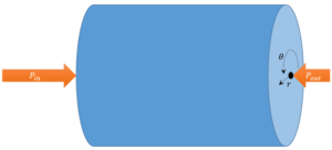
This example draws from the Faculty of Kahn video on Poiseuille’s law.  In this scenario, we imagine a horizontal pipe with an inlet pressure, $$P_{in}$$, and an outlet pressure, $$P_{out}$$, with $$P_{in} > P_{out}$$ and that the flow has had time to become steady.  Cylindrical geometry clearly suggests itself and we expect that the only flow is in the $$z$$-direction ($$V_r = V_{\theta} = 0$$) and its only variation is radial ($$V_z = V_z(r)$$).

As discussed in an earlier post, usually one must take care to differentiate the basis vectors as well as the components when setting up fluid equations in curvilinear coordinates.  However, the above assumptions are sufficiently limiting that only the $$z$$-component equation survives in the form

\[ \frac{d P}{d z} = \nu \frac{1}{r} \frac{d}{dr} \left( r \frac{d V_z}{dr} \right) \; . \]

The general solution to this is

\[ V_z(r) = \frac{P_{in} – P_{out}}{4 \mu L} r^2 + C_1 \ln r + C_2 \; .\]

The constants of integration follow from a boundary condition that requires $$V_z(r=0)$$ to be finite and the usual no-slip boundary condition at the walls.  The final form is then

\[ V_z(r) = \frac{P_{in} – P_{out}}{4 \mu L}(r^2 – R^2) \; .\]

Integrating this form over the surface area of the pipe gives the famous Poisueille flow rate relationship that says, for a given flow rate, the pressure differential is inversely proportional to the radius to the fourth power.  This relationship has profound consequences in the field of medicine.

Prandtl’s Boundary Layer

This month’s column begins a new chapter in the ongoing study of fluid dynamics.  Up to this point, the general equations of fluid motion have been derived from Newton’s laws using the transformation between a fluid-following viewpoint (Lagrangian point-of-view) and a field concept (Eulerian point-of-view).  General considerations of mass conservation and the principles of momentum and energy led to a system of non-linear partial differential equations.  Ignoring viscosity allowed the equations to simplify to Euler’s equations for an ideal fluid and several specific examples drove home some of the kinematics, dynamics, and methods of solution.

Unfortunately, the situation changes quite dramatically when viscosity is brought back into consideration and the full Navier-Stokes equations (which are themselves something of a simplification) begin to stare back from the page.  What is the general mode of attack, and how does one think about the solutions that result?  The enormous difficulty of finding solutions becomes even more acute when two facts are driven home.  First, it is extremely difficult to find solutions for the simpler set of equations for an ideal fluid, and the solutions shown to date (e.g. the Rankine Vortex), complicated as they may seem, are special cases passed down from one generation to the next precisely because they had a solution.  Second, general analytic solutions remain elusive nearly 200 years after Navier first derived these equations in 1822 despite millions of dollars offered to those who could derive such solutions.

To set the stage for an exploration that will consume many columns to come, this installment will present some of the observations and follow many of the arguments gleaned from the article Ludwig Prandtl’s Boundary Layer by John D. Anderson Jr published in the December 2005 issue of Physics Today.

According to Anderson, Ludwig Prandtl

revolutionized fluid dynamics with a very simple to understand and yet highly non-intuitive concept of the boundary layer that exists in a fluid near a rigid surface.

To understand the importance of Prandtl’s result one has to start the story in the latter half of the 18th century, around the time Euler derived the ideal fluid equations bearing his name.  The French mathematician Jean le Rond d’Alembert derived a paradox associated with ideal fluid flow.  He proved that, for an incompressible fluid with no viscosity (i.e., an ideal fluid), the drag force on an object placed within this flow, moving with constant relative velocity with respect to the fluid, is identically zero, an obviously incorrect result.

Acheson presents a mathematical derivation of d’Alembert’s paradox In Section 4.13 of his book Elementary Fluid Dynamics.  This derivation examines the force and momentum balance in the fluid and, using Bernoulli’s streamline theorem, concludes that, for the fluid to be moving at a uniform speed far upstream and far downstream from the body, the drag force on the body must vanish.  This result contradicts everyday observations about the motion of solid objects in air or water.

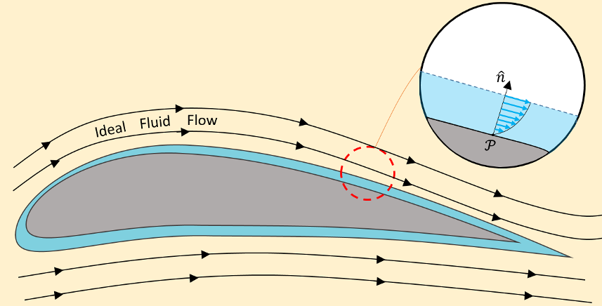
Clearly something was wrong with the theory of ideal fluid, but the specific root of the problem escaped identification for roughly 150 years until Prandtl introduced his boundary layer at a conference in 1904.  The modern picture of the boundary layer is best understood in terms of the motion of air over a cambered wing as shown in the figure below (based on Figure 2 of Anderson).

Away from the wing, the ideal fluid model works well in describing the streamlines.  However, close to the wing’s surface, viscous effects become dominant in a thin layer whose base attaches to the wing’s surface.  This no-slip condition demands that the fluid be at rest at the surface and that the fluid velocity rapidly rise from zero (where the layer attaches to the wing) to the ‘free stream’ velocity of the bulk inviscid flow outside the layer (shown in the inset).  In this way, d’Alembert’s paradox is conceptually resolved.  The drag force is non-zero, as observed, and the bulk flow is inviscid or ideal (depending on whether one allows the viscosity-free flow to be compressible or not), as observed, but the mathematical conditions by which d’Alembert derived the paradox are not true everywhere – the thin boundary layer makes all the difference.

Prandtl also predicted that, in certain cases, this layer can separate from the surface, which can cause additional drag.  To quote Prandtl

…there ought to be a layer of fluid which, having been set in rotation by the friction on the wall, insinuates itself into the free fluid, transforming completely the motion of the latter, and therefore playing there the same part as the Helmholtz surfaces of discontinuity.

Indeed, modern theory classifies the boundary layer behavior as falling into two broad classes.  Laminar motion describes the flow when the layer stays fixed to the surface.  Turbulent motion describes the flow when the layer separates and produces vortices in wake.  Laminar flow produces less drag than turbulent flow but it is unstable and thus harder to produce or control.  Turbulence changes the characteristics of the flow far from the surface causing additional drag.

In addition to these two critical physical observations, Anderson points out that the concept of the boundary layer also enabled the first quantitative calculations of aerodynamic drag.  The reason for this is that the boundary layer equations exhibit an entirely different type of mathematical behaviors than the equations describing the bulk flow outside.  Although both sets of equations are coupled, nonlinear, partial differential equations, the Navier-Stokes equations used to describe the bulk flow external to the layer are elliptic (at least when the flow is subsonic) while the simplification of these equations in the boundary layer are parabolic.  This distinction allows the solution methods used to describe the bulk motion to ‘decoupled’ from the methods used to describe the drag and since the methods for solving parabolic equations are much easier to deal with than those for elliptic equations real progress can be made.

What is particularly amazing about Prandtl’s contribution is that the original presentation in 1904 lasted no longer than 10 minutes.  I would say that the return on investment resulting from that rather short talk have been nothing short of phenomenal.

Streams, Streaks, Paths, and Flows

One of the more difficult things for any student of fluid dynamics to understand is the distinction between streamlines and streaklines and pathlines.  It ranks up there with mastering the difference between the Eulerian and Lagrangian viewpoints and, in fact, the same difficulty underpins both – the ability to tell the difference between an attribute of the field (Eulerian point-of-view) and an attribute of the particle or fluid element (Lagrangian point-of-view).  And, I’ll confess, that even though I understand the definitions, it isn’t always obvious how to apply them in different contexts.

Wikipedia has a somewhat useful article on the distinction between streamlines, streaklines, and pathlines but the math presented obscures the underlying physics and the foundation (either directly or by reference) is sorely lacking.

The first thing to note is that if the flow is steady, then all three lines result in the same trace in the fluid.  This is because each fluid element, flowing through a given point, follows exactly the same trajectory as the fluid element that precedes it or follows it.  The distinction between these lines (and possibly a few more differently defined traces) comes when the flow is unsteady (varies in time).

The formal definitions of these lines is as follows:

  • Streamline – a trace formed so that it is everywhere tangent to the velocity field of some local region of the fluid at a given time
  • Streakline – a trace of the front of all fluid elements, at a given time, that originated from the same physical place (for example a nozzle that flows smoke into a wind tunnel)
  • Pathline – a trace of the motion through time of a particular fluid element

These formal definitions don’t do a lot to promote understanding the situation.  So, we turn to an introductory diagram to explain the difference between streakline and pathline (streamlines will be discussed below) and then we will look at a simple example of unsteady flow to see the mathematical difference of all three.

Consider fluid starting to come out of a garden hose as the faucet is turned on.  The flow may start weakly and then climb until it levels off at the steady state value.  Below is a diagram of such a situation (inspired by the lecture from the Cowan Academy).  The individual pathlines are quite different and the time the fluid elements came through the outlet of the hose are different.  But their motion is stopped at a common time and the line joining them is the streakline.  It is particularly useful in that it represents an experiment that can be performed and measured.

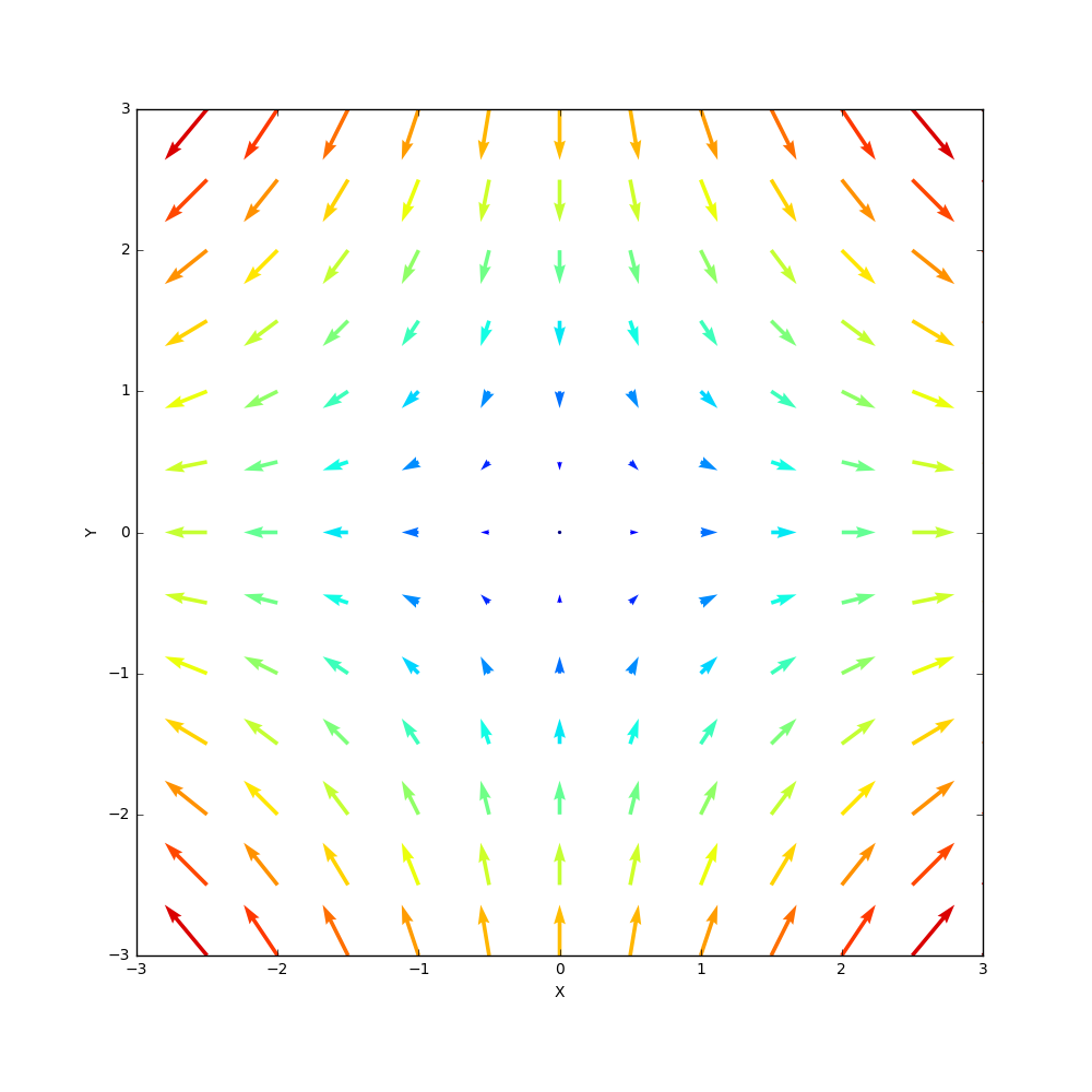
Streamlines are best shown using a quiver plot.  To be concrete consider the velocity field in 2 dimensions to be given by

\[ V_x= \alpha x \; \]

and

\[ V_y = -\alpha y \; ,\]

where $$\alpha$$ is some real number.  A plot of the flow velocity at a grid of points is called a quiver plot and the results for the flow above are (with $$\alpha = 1$$)

Note that the color of the vectors match their length with red corresponding the largest flow rate and blue the smallest, that they suggest that hyperbolic pattern with flow coming in along the y-axis and flowing along the x-axis, and the is a stagnation point at the origin where the fluid elements there are at rest.

Acheson, in Chapter 1 of Elementary Fluid Dynamics, has a nice problem associated with this flow that accentuates the difference between Lagrangian and Eulerian viewpoints.  In the Eulerian viewpoint, the concentration of a pollutant is given by

\[ c(x,y,t) = \beta x^2 y e^{-\alpha t} \; ,\]

which clearly varies in space and time and fades in strength at a given point as time progresses.  The question Acheson asks is does the concentration in a fluid element change.  To answer, we employ the material derivative, since it follows the flow of a given material element.  Taking the material derivative of the concentration gives

\[ \frac{D}{Dt} c(x,y,z) = \frac{\partial c(x,y,t)}{\partial t} + \left( \vec V \cdot \nabla \right) c(x,y,t) \; .\]

The right-hand side of the equation is a set of partial derivatives that, when expanded, is

\[ \partial_t c + \alpha x \partial_x c – \alpha y \partial_y c = -\alpha \beta x^2 y e^{-\alpha t} + 2 \alpha \beta x^2 y e^{-\alpha t} – \alpha \beta x^2 y e^{-\alpha t} = 0 \; . \]

So, the concentration of a fluid element is constant.  The reason the concentration decays in strength at a given point is simply that the flow shunts the more polluted elements away from any point and towards infinity.  Alternatively, one can use Lagrangian coordinates to describe the flow.  The position of a given fluid element is given by

\[ x = X e^{\alpha t} \; \; y = Y e^{-\alpha t} \; , \]

where $$X$$ and $$Y$$ are the x- and y-position of the fluid element at $$t=0$$.  In terms of these coordinates the concentration of a fluid element is

\[ c = \beta X^2 e^{-2 \alpha t} Y e^{\alpha t} e^{\alpha t} = \beta X^2 Y \; ,\]

which is manifestly time independent.

With this warm up exercise under our belt, let’s look at an unsteady flow where the difference between streamlines and pathlines becomes obvious.

Consider the flow

\[ V_x = V_{x_0} \; \; V_y = k t \; \]

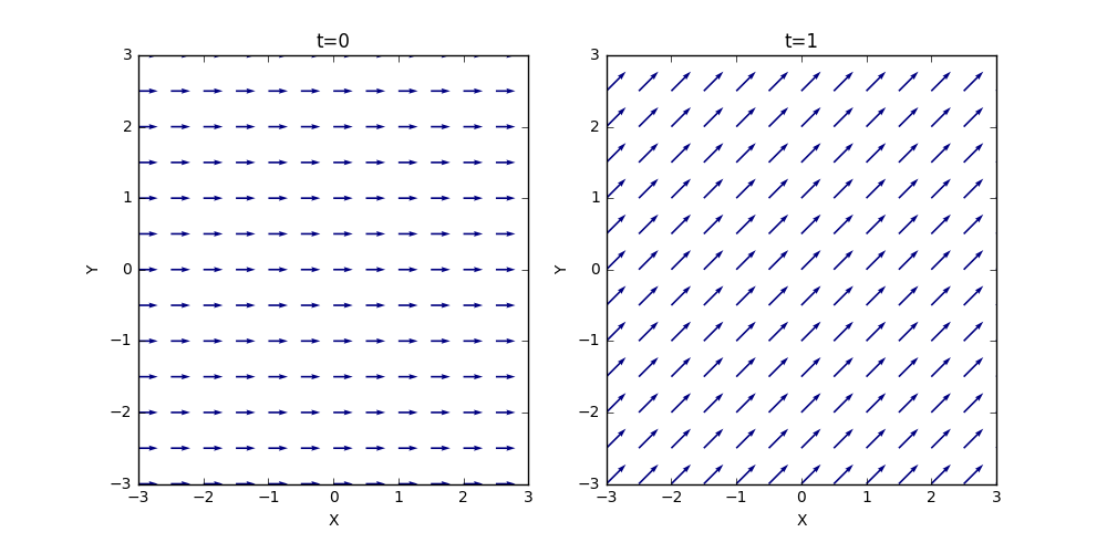
The quiver plots for two different times are shown here (with $$V_{x_0} = 1$$ and $$k=1$$).

In both cases, the streamlines are straight lines but with a time varying slope, as evidenced by the different slopes at different times.

The pathlines come from integrating

\[ \frac{\partial x}{\partial t} = V_{x_0} \;\; \textrm{and} \;\; \frac{\partial y}{\partial t} = k t \; .\]

Performing the integration and and setting the integration constants ($$x(t=0) = X$$ and $$y(t=0) = Y $$) to zero gives

\[ x(t) = V_{x_0} t \;\; \textrm{and} \;\; y(t) = \frac{1}{2} k t^2 \; .\]

Solving the first equation for $$t$$ and substituting into the second equation gives the geometric path of

\[ y = \frac{1}{2} \frac{k}{V_{x_0}^2} x^2 \; , \]

which shows that the particles follow a parabolic pathline even though the streamlines are always linear.

Ideal Fluids Closeout

This month’s column closes out the study of ideal fluids. The focus will be on two particular results that have only been touched upon briefly in other posts: 1) why the energy equation plays no role in solving flows for a given configuration and 2) what can happen when the density is not assumed to be constant. The latter point will only be touched upon in terms of how the relaxation of this constraint modifies the vorticity. The aim of this column is to provide a better understanding of how the physics of vortex generation and flow changes as we move from ideal fluids to viscous fluids. As a result, the analysis in this post and two preceding ones should serve as a baseline against the results for similar situations that arise from the Navier-Stokes equations. This post is strongly influenced by David Acheson’s Elementary Fluid Mechanics.

To start, let’s look at the momentum equation. In order to make this post self-contained, details will be repeated from other posts. In non-conservation form, the momentum equation is

\[ \rho \frac{D {\vec u}}{D t} = -\nabla P – \rho \vec g \; , \]

which is easy to remember based since it looks like Newton’s law. However, to really understand the content, we need to expand the material derivative to get

\[ \rho \left( \partial_t \vec u + (\vec u \cdot \nabla) \vec u \right) = -\nabla P – \rho \vec g \; .\]

The next step is to use the vector identity

\[ ( \vec u \cdot \nabla ) \vec u = \nabla \times (\nabla \times \vec u) – \frac{1}{2} \nabla( u^2 ) ;, \]

and to identify the vorticity as $$\vec \omega = \nabla \times \vec u$$.

Substituting these results back into the expanded momentum equation, gives

\[ \rho \left( \partial_t \vec u + \nabla \times \vec \omega \right) = -\nabla P – \rho \vec g – \frac{1}{2} \nabla (u^2) \; .\]

Now we take the dot product of the above equation with $$\vec u$$ to get

\[ \rho \partial_t \left( \frac{d}{dt} \frac{1}{2} u^2 \right) = – \vec u \cdot \nabla (P + gz) – \frac{1}{2} \vec u \cdot \nabla (u^2) \; .\]

Now we employ the vector identity

\[ \vec u \cdot \nabla H = H \nabla \cdot \vec u – \nabla \cdot (H \vec u) \; , \]

where $$H$$ is shorthand defined by

\[ H \equiv P + \rho z g + \frac{1}{2} u^2 \; .\]
Substituting this result in gives, mindful of the incompressibility of the fluid, $$\nabla \cdot \vec u$$, gives

\[ \partial_t \left( \frac{1}{2} \rho u^2 \right) = -\nabla \cdot \left[ H \vec u \right] \; . \]

In some sense, we are done, since the left-hand side has the power (time derivative of the kinetic energy) and the right-hand side has the flow of energy out of the fluid, since $$H$$ contains the energy density in the form of pressure (units of energy per unit volume), the gravitational potential energy density, and the kinetic energy density.

But a clear picture emerges if we employ the divergence theorem, which bring us to

\[ \frac{d}{dt} \int d {\mathcal Vol} \frac{1}{2} \rho u^2 = – \int d {\mathcal A} H \vec u \cdot {\hat n} \; , \]

which shows that the time rate of change of the kinetic energy of a fluid parcel is equal to the flow of the energy out from that parcel. Note that the energy here doesn’t involve any local thermodynamics and relies strictly on the bulk effects. That is why the solution to ideal fluid flow can ignore the energy equation and simply use momentum equation (as was done in the last two posts).

As we move to the Navier-Stokes equations, the presence of viscosity means that energy and momentum can flow between the smallest of fluid elements because viscosity implies that two fluid elements can interact in a ‘shearing’ fashion. Said differently, viscosity is a type of friction that excites internal degrees of freedom (as does temperature – but more on that in future posts).

Now, we look at the relaxing the assumption that an ideal fluid has constant density. Our starting point is Euler’s equation above, repeated here for convenience

\[ \partial_t \vec u + \vec \omega \times \vec u = -\frac{1}{\rho} \nabla \left( p + E_{mech} \right) \; ,\]

where $$E_{mech} = \Xi + 1/2 u^2$$ and $$\Xi$$ is the gravitational potential and the mass conservation equation

\[ \frac{D\rho}{Dt} + \rho \nabla \cdot {\vec u} = 0 \; . \]

Now take the curl of Euler’s equation to get
\[ \partial_t \vec \omega + \nabla \times \left( \vec \omega \times \vec u \right) = – \frac{1}{\rho} \nabla \times \vec F \; , \]

where $$\vec F = \nabla \left(p + E_{mech} \right)$$, for convenience.

Expand $$\nabla \left( \vec \omega \times \vec u \right)$$ as

\[ \nabla \times \left( \vec \omega \times \vec u \right) = (\vec u \cdot \nabla) \vec \omega – (\vec \omega \cdot \nabla ) \vec u + \omega (\nabla \cdot u) – \vec u (\nabla \cdot \vec \omega) \; .\]

If the fluid were incompressible $$\nabla \cdot \vec u = 0$$, but under these assumptions we need to keep this term, using the mass conservation to eliminate the divergence of the velocity in terms of the material derivative of the density. The one term that is identically zero is $$\vec u (\nabla \cdot \vec \omega)$$ since the gradient of a curl is zero.

The next ingredient is to use the identity

\[ \nabla \times \left( \frac{1}{\rho} \vec F \right) = \vec F \times \nabla \left( \frac{1}{\rho} \right) + \frac{1}{\rho} \nabla \times \vec F \]

Putting all these pieces together

\[ \frac{D}{Dt} \left( \frac{\vec \omega}{\rho} \right) = \left( \frac{\omega}{\rho} \cdot \nabla \right) \vec u – \frac{1}{\rho} \nabla \left(\frac{1}{\rho} \right) \times \nabla P \; \]

This equation generalizes the vorticity equation to compressible fluid flow. Note that if the pressure is a function of the density only, the gradient of the pressure is parallel to the gradient of the density and the second term on the right-hand vanishes.

Rankine Vortex

This month’s column is going to look at a simple model of a vortex called the Rankine vortex.  The model is extraordinarily simple and it is somewhat astonishing how well it matches results from real world observations.  Giaiotti and Stel provide vivid comparisons between the Doppler observations of tornado’s radial velocity distribution and the agreement is strong.   This, despite the fact, that the Rankine vortex is really an ideal fluid model that doesn’t carry over into the realm of the Navier-Stokes equations where viscosity is important.

The presentation here follows David Acheson’s textbook Elementary Fluid Dynamics with some inspiration and direction from a lecture by Luca Brandt on the Rankine Vortex available here.

The Rankine vortex consists of two parts: an inner core that moves as a rigid body and a vortex free exterior.  Mathematically, the Rankine vortex is specified as

\[ R = \left\{ \begin{array}{c} \Omega r \;\; r < a \\ \frac{\Omega a^2}{r} \; \; r >a \end{array} \right. \, \]

with $$u_r = u_z = 0$$.

By its geometry, the Rankine vortex demands us to work in cylindrical coordinates.  There are two steps that one must pay attention to in order to setup the problem.  First, by standard vector calculus results, the convective derivative is given by

\[ {\vec u} \cdot \nabla = u_r \partial_r + \frac{u_{\theta}}{r} \partial_\theta + u_z \partial_z \; .\]

Second, the fluid velocity, given in terms of the radial, azimuthal, and vertical unit vectors, is

\[ {\vec u} = u_r {\hat e}_r + u_\theta {\hat e}_\theta + u_z {\hat e}_z \; ,\]

with the realization that the radial and azimuthal unit vectors change as a function of space according to

\[ \partial_\theta {\hat e_r} = {\hat e}_\theta \]

and

\[ \partial_\theta {\hat e_\theta} = -{\hat e}_r \; .\].

Now applying the convective derivative to the velocity,

\[ (\vec u \cdot \nabla) \left[ u_r {\hat e}_r + u_\theta {\hat e}_\theta + u_z {\hat e}_z \right] \; ,\]

formally, gives a lot of terms

\[ (\vec u \cdot \nabla) {\vec u} = \left[ u_r \partial_r u_r + \frac{u_\theta}{r} \partial_\theta u_r + u_z \partial_z u_r – \frac{u_\theta^2}{r} \right] {\hat e_r} \\ + \left[ u_r \partial_r u_\theta + \frac{u_r u_\theta}{r} + \frac{u_\theta}{r} \partial_\theta u_\theta + u_z \partial_z u_\theta \right] {\hat e}_\theta \\ + \left[ u_r \partial_r u_z + \frac{u_\theta}{r} \partial_\theta u_z + u_z \partial_z u_z \right] {\hat e}_z \; ,\]

but, by the assumptions in the Rankine vortex, most are zero.  Putting all these pieces together results in the convective derivative taking the form

\[ \left( \vec u \cdot \nabla \right) \vec u = -\frac{u_\theta^2}{r} {\hat e}_r \; . \]

Given that the flow is steady, the resulting model is the following partial, coupled, differential equations

\[ -\rho \frac{u_\theta^2}{r} {\hat e}_r = -\frac{\partial P}{\partial r} {\hat e}_r \; , \]

\[ 0 = – \frac{\partial P}{\partial \theta} {\hat e}_\theta \; , \]

and

\[ 0 = \left( -\frac{\partial P}{\partial z} – \rho g \right) {\hat e}_z \; . \]

The $$\theta$$ equation merely tells us that $$P = P(r,z)$$.  The $$z$$ equation is easily solved for both the inner and outer regions of the vortex because there is no discontinuity.  This gives

\[ P(r,z) = – \rho g z + f(r) \; .\]

The radial profile requires a bit more work as the inner and outer regions have to have separate integrations.  For the inner

\[ \frac{1}{\rho} \frac{\partial P}{\partial r} = \frac{ \Omega^2 r^2}{r} = \Omega^2 r \;\; r < a \; . \] In similar fashion, the outer integration yields \[ \frac{1}{\rho} \frac{\partial P}{\partial r} = \frac{\frac{\Omega^2 a^r}{r^2}}{r} = \frac{\Omega^2 a^4}{r^3} \;\; r > a \; . \]

Solving both of these equations gives

\[ P(r,z) = \left\{ \begin{array}{c} \frac{1}{2} \rho \Omega^2 r^2 – \rho g z + C_1 \;\; r < a \\ – \frac{1}{2} \rho \frac{\Omega^2 a^4}{r^2} – \rho g z + C_2 \;\; r > a \end{array} \right. \]

Continuity at $$r=a$$ gives

\[ -\frac{1}{2} \rho \Omega^2 a^2 – \rho g z + C_2 = \frac{1}{2} \rho \Omega^2 a^2 – \rho g z + C_1 \; , \]

which leads to

\[ C_2 – C_1 = \rho \Omega^2 a^2 \; .\]

We can determine the pressure difference between the core and far from the core by comparing the interrogating the above result.  The pressure at the core is

\[ P(0,z) = -\rho g z + C_1 \; \]

and the pressure at infinity is

\[ P(\infty,z) = – \rho g z + C_2 \; .\]

Their difference is

\[ P(\infty,z) – P(0,z) = C_2 – C_1 = \rho \Omega^2 a^2 \; , \]

which explains why the pressure at the center of a tornado (vortex) is lower than the pressure far from the core.

The free surface (the shape) of the vortex as a function of radius is found by setting $$P(r,z) = P_0$$ with the height being assumed to be $$z_0$$ at $$r=0$$.

Vorticity

The last post developed the basic theory of an ideal fluid, teased out Bernoulli’s theorem, and introduced the concept of fluid vorticity. While these basic results are fairly simple there are certain caveats that need to be observed and applications of this theory can be tricky if they are not. To illustrate some of the complexities that can arise when careful thinking is not exercised, this post considers the rotating bucket problem discussed in Acheson’s Elementary Fluid Dynamics.

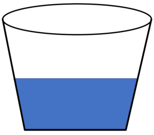
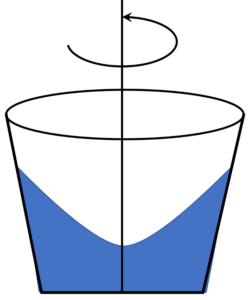
To begin, start with the simpler physical situation with the bucket filled with water that is sitting quietly on a table. The free surface of the water has a flat profile whose normal is parallel with the vertical, a configuration that is consistent with everyone’s experience in drinking out of a glass.

Now if we imagine that the bucket is then rotated about its vertical axis, our intuition says that the fluid will tend to migrate outwards leading to a parabolic-like profile that is lower at the center of the bucket and higher at the edges.

To mathematically prove our intuition, assume that the bucket spins uniformly so that its angular velocity is given by

\[ \vec \Omega = \left[ \begin{array}{c} 0 \\ 0 \\ \Omega \end{array} \right] \; \]

with the resulting fluid velocity being

\[ \vec V = \vec \Omega \times \vec r = \left[ \begin{array}{c} -\Omega y \\ \Omega x \\ 0 \end{array} \right] \; .\]

The fluid vorticity is

\[ \vec \omega = \nabla \times \vec V = \left[ \begin{array}{c} 0 \\ 0 \\ 2 \Omega \end{array} \right] \; .\]

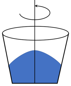
Now we have two paths that we may try in incorporating these kinematic assumptions in the description of the free surface of the fluid: direct solution of Euler’s equation or application of Bernoulli’s theorem. The latter is certainly seems more attractive as it requires fewer steps but that it leads to a contradiction whose explanation proves to be informative. The direct solution is harder to implement but yields a solution consistent with our intuition. But, for the sake of pedagogy, let’s try Bernoulli’s theorem first.
The free surface of the fluid is defined by the locus of points in the fluid with a common pressure equal to atmospheric pressure. The fluid density is also assumed to be constant (a defining assumption of the ideal fluid theory we are using). Applying Bernoulli’s theorem, which reads

\[ \frac{P}{\rho} + g z + \frac{1}{2} \Omega \left( x^2 + y^2 \right) = C’ \; \]

to the entire fluid gives

\[ g z + \frac{1}{2} \Omega \left( x^2 + y^2 \right) = C \; .\]

Solving for z yields

\[ z = C – \frac{1}{2} \frac{\Omega^2}{g} \left( x^2 + y^2 \right) \; ,\]

which is a free surface that is higher at the middle than it is at the edges, in clear contradiction to our experience and intuition.

So, what went wrong? The answer is that the flow is not irrotational (the vorticity presented above is not zero). The assumption that Bernoulli’s equation describes a quantity that is constant throughout the entire fluid doesn’t apply. The flow is steady, so $$(\vec V \cdot \nabla) H = 0$$ still holds, implying that $$H$$ is constant along a given streamline but there is no way to know how $$H$$ varies as we move from one fluid element to another. So, the blind application of Bernoulli’s theorem to every fluid element is simply not correct. Again this is a key reminder of the distinction between a quantity that stays constant along a streamline as the fluid flows and a quantity that is constant throughout every part of the fluid.

The correct way to solve this problem is to go back to Euler’s equation in component form. The make it a bit easier to apply, first compute some intermediate results. The nonlinear term in Euler’s equation becomes

\[ \left( \vec V \cdot \nabla \right) \vec V = \left( -\Omega y \partial_x + \Omega x \partial_y \right) \left[ \begin{array}{c} -\Omega y \\ \Omega x \\ 0 \end{array} \right] = \left[ \begin{array}{c} – \Omega^2 x \\ -\Omega^2 y \\ 0 \end{array} \right] \; . \]

The incompressibility relation

\[ \nabla \cdot \vec V = \partial_x (-\Omega y) + \partial_y (\Omega x) = 0 \; \]

is automatically satisfied so we can ignore it going forward.

Euler’s equation then becomes

\[ \left[ \begin{array}{c} -\Omega^2 x \\ -\Omega^2 y \\ 0 \end{array} \right] = -\frac{1}{\rho} \left[ \begin{array}{c} \partial_x P \\ \partial_y P \\ \partial_z P \end{array} \right] + \left[ \begin{array}{c} 0 \\ 0 \\ -g \end{array} \right] \; , \]

which, when simplified, becomes the three coupled partial differential equations

\[ \partial_x P = \rho \Omega^2 x \; , \]

\[ \partial_y P = \rho \Omega^2 y \; , \]

and

\[ \partial_x P = -\rho g \; . \]

Assuming the pressure to be a separable function of all three coordinates, we can integrate the first equation to get

\[ P = \frac{1}{2} \rho \Omega^2 x^2 + F(y,z) \; . \]

The second equation then becomes

\[ \partial_y P = \partial_y F(y,z) = \rho \Omega^2 y \; , \]

which results in

\[ F(y,z) = \frac{1}{2} \rho \Omega^2 y^2 + G(z) \; .\]

Finally, the third equation becomes

\[ \partial_z P = \partial_z G(z) = -\rho g \; , \]

which has the solution

\[ G(z) = -\rho g z \; ,\]

giving a final form of the pressure as

\[ P(x,y,z) = \frac{1}{2} \rho \Omega^2 x^2 + \frac{1}{2} \rho \Omega^2 y^2 – \rho g z \; .\]

Setting the pressure equal to the constant atmospheric pressure yields

\[ \frac{P_{atmosphere}}{\rho g} = const = \frac{1}{2} \frac{\Omega^2}{g} \left( x^2 + y^2 \right) – z \; \]

or

\[ z = \frac{1}{2} \frac{\Omega^2}{g} \left( x^2 + y^2 \right) – const \; ,\]

which is exactly the parabolic shape our intuition and common experience demands.

The lesson here is the vorticity is a key quantity that provides invaluable insight into fluid motion.

Bernoulli’s Principle

The Navier-Stokes equation derived in the previous post represents a springboard for the study of Newtonian fluids in a variety of scenarios. Because of the complexity of the equations of fluid mechanics, even this ‘approximation’ represents a degree of complexity that has yet to be completely understood. In fact, questions about the structure and existence of solutions to the Navier-Stokes equations are considered to be so important that the Clay Mathematics Institute is offering a Millennium Prize for proofs associated with this system as a step towards understanding turbulence.

As a result, the next set of posts will focus on subsets of these equations with the examples often being even more simplified. The hope is by looking at simple scenarios a degree of intuition may be developed. This approach is largely influenced by the fine book Elementary Fluid Mechanics by Acheson.

The first block of these will be concerned with the original jewel in the mathematical modeling of fluids in the 18th and 19th centuries – an ideal fluid.

An ideal fluid is a drastic simplification to the fluid flow model in which internal transports of energy or momentum between fluid elements are ignored. Thus the internal energy of a fluid element remains constant during the flow and its kinetic energy and momentum change only due to the external forces. In addition, the flow is assumed to be incompressible ($$\nabla \cdot \vec V = 0$$), meaning that the density of any fluid element remains constant during the flow and, as a further simplification, each fluid element will be assigned the same value of density. Note that these are two distinct assumptions about the density, a point Acheson goes to great lengths to emphasize in his discussion on pages 6, 23-4, and, in particular, 356, where he states quite clearly that:

$$D\rho/Dt = 0$$ does not mean that $$\rho$$ is a constant; it means that $$\rho$$ is conserved by each individual fluid element, and this makes sense, as each element conserves both its mass and (if $${\mathbf \nabla} \cdot {\mathbf u} = 0$$) its volume.

Despite these seemingly drastic simplifications, there are numerous ordinary, terrestrial applications of the theory. The most common one would be the flow of water in a variety of ‘household’ circumstances. It should be noted that the assumption of incompressibility and a constant, homogeneous density is actually a better assumption than that the fluid has no viscosity (i.e. is inviscid). Fluid compressibility needs to be more carefully considered only when the flow speeds near the speed of sound in the fluid. Nonetheless, the ideal fluid was the jewel of yesteryear mostly because these assumptions actually meant one could solve a problem, even if the problem only partially matched what was physically observed. This gap between what can be modeled and what is observed will become a common theme in the posts to follow.

To get the equations for an ideal fluid, start with the Navier-Stokes equations

\[ \rho \frac{D \vec V}{D t} = – \nabla P + \mu^2 \nabla \vec V + \frac{1}{3} \mu \nabla (\nabla \cdot \vec V) + \rho \vec g \; , \]

(where the material derivative $$D/Dt = \partial_t + \vec V \cdot \nabla$$), and set the viscosity $$\mu$$ equal to zero, yielding Euler’s equations

\[ \frac{D \vec V}{dt} = -\frac{1}{\rho} \nabla P + \vec g \; .\]

In addition to these equations, we always have the continuity equation

\[ \frac{D \rho}{d t} + \rho \nabla \cdot \vec V = 0 \; ,\]

which, given the two incompressibility assumptions, simplifies to

\[ \nabla \cdot \vec V = 0 \; \]

and

\[ \rho = \mathrm{constant} \; .\]

Taken together, these are a set of 4 equations in the 4 unknowns $$\vec V$$ and $$P$$ (with $$\rho$$ assumed to be known for the particular situation).

Even in this simple form, the equations can be quite hard to solve as can be more readily seen if the equations are put into component form (after expanding the material derivative):

\[ \partial_t V_x + V_x \partial_x V_x + V_y \partial_y V_x + V_z \partial_z V_x = – \frac{1}{\rho} \partial_x P \; ,\]

\[ \partial_t V_y + V_x \partial_x V_y + V_y \partial_y V_y + V_z \partial_z V_y = – \frac{1}{\rho} \partial_y P \; ,\]

\[ \partial_t V_z + V_x \partial_x V_z + V_y \partial_y V_z + V_z \partial_z V_z = – \frac{1}{\rho} \partial_z P \; ,\]

and

\[ \partial_x V_x + \partial_y V_y + \partial_z V_z = 0 \; .\]

Obviously, these equations are not particularly illuminating, even for the great masters of the 18th and 19th centuries. It is remarkable then, that there is a very convenient simplification that was discovered by Daniel Bernoulli, called Bernoulli’s principle, which he published in 1738.

While Bernoulli didn’t have access to modern vector calculus (making his discovery all the more remarkable), we will not be too proud to employ it since it will make the derivation clearer and will serve as a springboard to subsequent discoveries.

Return to Euler’s equation

\[ \partial_t \vec V + (\vec V \cdot \nabla) \vec V = -\frac{1}{\rho} \nabla P + \vec g \; .\]

The most troublesome term is the nonlinear $$(\vec V \cdot \nabla) \vec V$$ term on the left-hand side. A convenient vector identity can be employed to separate this nonlinear term into solenoidal and irrotational pieces

\[ (\vec V \cdot \nabla) \vec V = (\nabla \times \vec V) \times \vec V + \nabla \left( \frac{1}{2} \vec V^2 \right) \].

We know define the vorticity vector (more about this in the next post) as

\[ \vec \omega = \nabla \times \vec V \; .\]

Euler’s equation now becomes (moving the irrotational term to the right-hand side)

\[ \partial_t \vec V + \vec \omega \times \vec V = -\nabla \left( \frac{1}{2} \vec V^2 \right) -\frac{1}{\rho} \nabla P + \vec g \; .\]

Since the gravitational force can also be derived from the gradient of a potential $$\vec g = -\nabla \chi$$, Euler’s equation can finally be written as

\[ \partial_t \vec V + \vec \omega \times \vec V = -\nabla H \; , \]

where

\[ H = \frac{P}{\rho} + \chi + \frac{1}{2} \vec V^2 \; \]

Now if the flow is steady, the time variation can be set to zero. Taking the dot product of both sides with $$\vec V$$ and noting that $$\vec V \cdot (\vec \omega \times \vec V) = \omega \cdot (\vec V \times \vec V) = 0$$ yields

\[ \vec V \cdot (\nabla H) = (\vec V \cdot \nabla) H = 0 \; .\]

The physical interpretation of this equation is that the value of H is conserved, for a given fluid element, as it flows. This, then, is Bernoulli’s principle which states that changes of a fluid element’s flow speed are balanced by corresponding changes in pressure or gravitational potential energy, such that the initial value of H remains constant.
Bernoulli’s principle precisely describes how high flow from a faucet, a garden hose, or fountain can reach when pushed upward from an orifice when it emerges with a particular pressure and speed. It represents the simplest form of energy conservation for a fluid.

A simple example of the Venturi tube will illustrate some of the applications. Consider the pipe shown below (assume cylindrical symmetry).

Let the inlet area and speed be $$A_1$$ and $$V_1$$, respectively, and the area and speed at the middle of the pipe be $$A_2$$ and $$V_2$$. The question we can answer is what is the difference between the inlet pressure and the pressure at the center. Following any stream line (thin blue lines), we know that the mass of the fluid element is conserved and so the total inlet mass must be conserved. The continuity equation takes the form

\[ \rho_1 A_1 V_1 = \rho_2 A_2 V_2 \; , \]

for mass per unit time.

Using Bernoulli’s equation we also get

\[ \frac{P_1}{\rho_1} + \frac{1}{2} V_1^2 = \frac{P_2}{\rho_2} + \frac{1}{2} V_2^2 \; .\]

Now, for an ideal fluid, the density is constant, and we can solve for $$V_2$$ in terms of the known areas and inlet speed. Substituting this result in Bernoulli’s gives a pressure difference of

\[ P_1 – P_2 = \frac{1}{2} \rho V_1^2 \left[ \left( \frac{A_1}{A_2} \right)^2 – 1 \right] \; \]

Clearly showing that the pressure at the center of the tube is lower than at the inlet with the difference depending on the inlet speed and the ratio of the two cross-sectional areas. This tube is used in the Venturi meter to determine/monitor flow speeds.

Next post will examine the role that the vorticity plays in ideal fluid flow.

Newton and Navier-Stokes

This month’s column begins the process of narrowing down the general equations of fluid mechanics, developed over the last many columns, into a set of specific equations.  In particular, to make progress in describing specific situations, we must be able to relate the stress tensor to the state of the fluid.  This relation is analogous to the generalized Hooke’s law used in the study of elastic deformations.

While there are an amazingly large number of types of fluids out there in the world, this discussion and those that follow will be focused only on the simplest of these: Newtonian fluids for which there is a linear relationship between the applied shearing stress and the velocity gradients that result.  To further simplify matters, we shall also look only at the form of the Cauchy momentum equation for a Newtonian fluid, which is known by the famous name of the Navier-Stokes equation. The treatment here parallels the one found in An Introduction to Fluid Dynamics, by G.K. Batchelor.

There are interesting differences between a moving fluid and one at rest.  A fluid at rest necessarily exerts a normal stress independent of direction; no shear stresses are supported and the stress must to isotropic, leading to a very simple expression for the stress tensor

\[ T_{ij} = -p \, \delta_{ij} \; . \]

The parameter $$p$$ is the static fluid pressure, which can only be a function of position (e.g. the change in pressure with depth in a swimming pool).

Batchelor notes that there should be no expectation that this simple relation holds for a moving fluid, since, once in motion, the fluid can support shearing stress and will, in general, depart from isotropy.  Nonetheless, it helps to have a scalar quantity, similar to static pressure, that characterizes the “squeezing” of the fluid. This pressure is defined by averaging the normal component of stress over the surface of a small sphere centered on the position $$\vec x$$

\[ P = -\frac{1}{3} T_{ii} = – \frac{1}{3} T_{ij} \delta_{ij} = -\frac{1}{4 \pi} T_{ij} \int n_i n_j d \Omega(\vec n) \; , \]

where $$\vec n$$ is the normal to the surface of the sphere.  Batchelor emphasizes that $$P$$ is a mechanical definition with only a loose connection with thermodynamic notion of pressure, the latter requiring some notion of equilibrium, which is absent when the fluid is in motion.  Nonetheless, $$P$$ is a useful quantity because it is experimentally accessible from measurements of force and momentum (or, more accurately, from typical mechanical measurements that allow the inference of force and momentum).

Since $$P$$ is associated with the isotropic portion of the stress, it is mathematically convenient to decompose the stress tensor as

\[ T_{ij} = -P \delta_{ij} + d_{ij} \; \]

where $$d_{ij}$$ is a traceless tensor, known as the deviatoric stress, whose non-zero nature is due solely to the fluid motion.  It represents the internal transport of momentum, which can manifest itself as friction.

It is at this point, where the assumption that the fluid is Newtonian is brought to bear by expressing the deviatoric stress as being linearly proportional to the velocity gradient by

\[ d_{ij} = A_{ijk \ell} \frac{\partial V_k}{\partial x_\ell} \; \]

Where the tensor $$A_{ijk \ell}$$ depends on the local state of the fluid but not directly on the velocity distribution.  Since the deviatoric stress is symmetric in its indices we can conclude that $${\mathbf A}$$ is symmetric in its first two indices.

Next, we can decompose the velocity gradient as

\[ \frac{\partial V_k}{\partial x_{\ell}} = e_{k \ell} – \frac{1}{2} \epsilon_{k \ell m} \omega_m \; , \]

where $$e_{k \ell} = 1/2 (\partial_k V_\ell + \partial_\ell V_k)$$ is a symmetric tensor and $$\omega_m$$ is the vorticity defined, in terms of the anti-symmetric portion of the velocity gradient, by

\[ \omega_m = \epsilon_{m n p} \frac{1}{2} \left(\partial_n V_p – \partial_p V_n \right) \; .\]

The penultimate simplifying assumption in this long cavalcade of reductions, is to confine the discussion to gases and simple liquids, in which the ‘shape’ of the molecules is nearly spherical.  This assumption allows us to conclude that the deviatoric stress is independent of the orientation of the fluid element, thus imposing rotational symmetry on $$A_{i j k \ell}$$. This assumption should be viewed in contrast to a fluid whose molecular constituents are long chains and that, as a result, exhibits a preferred (i.e. easy) axis.

Imposition of rotational symmetry on $${\mathbf A}$$ means that it can only have the following general form

\[ A_{i j k \ell} = \mu \delta_{ik} \delta_{j \ell} + \mu’ \delta_{i\ell} \delta_{jk} + \mu^{\prime\prime} \delta_{ij}\delta_{kl} \; .\]

The ‘mu’ parameters describe the viscosity that arises from various shearing motions.  Because of the symmetries imposed on $${\mathbf d}$$ and upon $${\mathbf A}$$, they are not all independent.  Since $${\mathbf A}$$ is symmetric in its first two indices $$ \mu = \mu’$$ and

\[ A_{i j k \ell} = \mu ( \delta_{ik} \delta_{j \ell} + \delta_{i \ell} \delta_{jk} )+ \mu^{\prime\prime} \delta_{ij} \delta_{k\ell} \\ = \mu (\delta_{i \ell} \delta_{jk} + \delta_{ik} \delta_{j\ell} ) + \mu^{\prime\prime} \delta_{ij}\delta_{ \ell k} = A_{ij \ell k} \; ,\]

Clearly showing that $${\mathbf A}$$ is now symmetric in its third and fourth indices as well.  Note that this symmetry was made manifest by swapping the first and second terms and using the symmetry of the Kronecker delta in the term.

Armed with this knowledge of $${\mathbf A}$$, we return to the relation between the deviatoric stress and the velocity gradient to find

\[ d_{ij} = A_{ijk \ell} \frac{\partial u_k}{\partial x_{\ell}} = A_{ijk \ell} e_{k \ell} = \left[ \mu(\delta_{ik} \delta_{j\ell} + \delta_{i\ell} \delta_{jk}) + \mu^{\prime\prime} \delta_{ij} \delta_{k\ell} \right] e_{k\ell} \\ = 2 \mu e_{ij} + \mu^{\prime\prime} Tr({\mathbf e} \delta_{ij}) \; . \]

Note that the second equality follows from the symmetry of $${\mathbf A}$$ in its last two indices, the third equality by substituting in the specific form of $${\mathbf A}$$ and the final one by multiplying the contractions out and defining $$e_{kk} \equiv Tr({\mathbf e})$$.  The final step is to note that, since $${\mathbf d}$$ is traceless

\[ Tr({\mathbf d}) = 2 \mu Tr({\mathbf e}) + 3 \mu^{\prime\prime} Tr({\mathbf e}) = 0 \; \]

implying that $$\mu^{\prime\prime} = \, – 2/3 \mu$$.

After all this work, we now have a form of the deviatoric stress $${\mathbf d}$$ in terms of the symmetric part $${\mathbf e}$$ of the velocity gradient given by

\[ d_{ij} = 2 \mu \left( e_{ij} – \frac{1}{3} Tr({\mathbf e}) \delta_{ij} \right) \; . \]

This expression was the result of many hands in the mid-1800s, but often bears the name of Saint-Venant who derived essentially as was done above in 1843.

Suppose that the only non-zero velocity gradient component is $$\partial u_x/\partial y$$.  All components of deviatoric stress is zero except for the tangential stresses $$d_{xy} = d_{yx} = \mu \partial u_x/\partial y$$, which justifies identifying $$\mu$$ with the elementary definition of viscosity.

The Cauchy momentum equation (in conservative form) is now

\[ \frac{\partial \rho \vec V}{\partial t} + \nabla \cdot (\rho \vec V \vec V) = \nabla \cdot \left[ -p {\mathbf 1} + 2 \mu \left( e_{ij} – \frac{1}{3} Tr({\mathbf e}) \delta_{ij} \right) \right] + \vec f_b \; . \]

Finally, assume that the viscosity is a constant (that is we will initially confine ourselves to those cases where this is a very good approximation), to get the Navier-Stokes equations

\[ \frac{\partial \rho \vec V}{\partial t} + \nabla \cdot (\rho \vec V \vec V) = – \nabla p + \mu \nabla^2 \vec V + \frac{1}{3} \mu \nabla (\nabla \cdot \vec V) + \rho \vec g \; , \]

where we used $$Tr({\mathbf e}) = \nabla \cdot \vec V$$ and we specialized to gravity as the only body force: $$\vec f_b = \rho \vec g$$.  These cosmetic changes are design to facilitate comparison with the usual way the Navier-Stokes equations are written.

Next column will begin looking at information that can be interrogated from these equations and the solutions in simple situations.