Latest Posts

Plasma Waves: Part 4 – Parallel Propagation in Cold Magnetized Plasmas

The last column established the basic equations describing waves in cold magnetized plasma and derived some of the general results that can be deduced without finding explicit solutions. This column begins the detailed examination of the explicit solutions that are supported.

The central relationship for this analysis is the tangent form of the dispersion relation

\[ \tan^2 \theta = -\frac{P(n^2-R)(n^2 – L)}{(Sn^2 – RL)(n^2 – P)} \; , \]

where $$\theta$$ is the angle between the direction of wave propagation and the magnetic field, $$n$$ is the index of refraction, and the terms $$S$$, $$P$$, $$R$$, and $$L$$ are

\[ S = 1 – \sum_s \frac{\omega_{ps}^2}{\omega^2 – \omega_{cs}^2} \; ,\]

\[ P = 1 – \sum_s \frac{\omega_{ps}^2}{\omega^2} \; ,\]

\[ R = 1 – \sum_s \frac{\omega_{ps}^2}{\omega(\omega+\omega_{cs})} \; ,\]

and

\[ L = 1 – \sum_s \frac{\omega_{ps}^2}{\omega(\omega-\omega_{cs})} \; ,\]

respectively.

Selecting a particular value of $$\theta$$ sets the propagation of the wave relative to the magnetic field and constrains the dispersion relation. There are three cases to examine: 1) parallel propagation, 2) perpendicular propagation, and 3) oblique propagation. This column will focus on parallel propagation.

In this case the wave moves along the magnetic field and $$\theta = 0$$. Since $$\tan \theta = 0$$, the propagation modes can be read off of the tangent form by simply finding the zeros of the right-hand side. Doing so yields

\[ P = 0 \; ,\]

\[ n^2 = R \; ,\]

and
\[ n^2 = L \; .\]

While the dispersion tensor

\[ \overleftrightarrow{D}(\vec n, \omega) = \left[ \begin{array}{ccc} S-n^2 & -i D & 0 \\ i D & S-n^2 &0 \\ 0 & 0 & P \end{array} \right] \; .\]

was useful for getting the characteristic equation, the matrix that gives the eigenvectors is the dielectric tensor (since $$n^2$$, in this case, is essentially the eigenvalue – at least for $$x$$ and $$y$$). The dielectric tensor’s form is

\[ \overleftrightarrow{K} = \left[ \begin{array}{ccc} S & -i D & 0 \\ i D & S &0 \\ 0 & 0 & P \end{array} \right] \; ,\]

where $$D = \frac{1}{2}( R – L )$$.

A simple analysis shows that the eigenvector corresponding to $$P=0$$ must have the form

\[ \vec E_{P} = \left[ \begin{array}{c} 0 \\ 0 \\ E_{P} \end{array} \right] \; ,\]

where $$E_P$$ is arbitrary.

This mode corresponds to a longitudinal wave at a frequency equal to $$\pm \omega_p$$, the combined plasma frequency of the system:

\[ P = 0 \Rightarrow \omega^2 = \sum_s \omega_{ps}^2 \; .\]

Since the wave is longitudinal it can’t be electromagnetic in origin and is, instead, associated with electrostatic fluctuations of the charge density along the magnetic field direction.

The eigenvectors for the other two modes require a bit more work but it is obvious that the corresponding eigenvectors can only have non-zero components along the $$x$$- and $$y$$-directions. Hence the structure of the wave is transverse, with the wave’s electric and magnetic fields perpendicular to the external magnetic field. Using wxMaxima, the eigenvector/eigenvalue pairs are given by:

\[ S + D = R: \left[ \begin{array}{c} 1 \\ i \\ 0 \end{array} \right] \]

and

\[ S – D = L: \left[ \begin{array}{c} 1 \\ -i \\ 0 \end{array} \right] \; .\]

The difference in the signs of the imaginary components correspond to the differences in handedness (hence the symbols $$R$$ and $$L$$ for right-handed and left-handed, respectively).

The usual convention for pulling out the handedness comes from multiplying the eigenvector by the time evolution $$e^{-i\omega t}$$ and taking the real part. For the $$R$$-mode, this process results in time dependence of

\[ E_x = E_0 \cos(\omega t) \]

and

\[ E_y = E_0 \sin(\omega t) \; ,\]

which shows that the electric field rotates in a counter-clockwise or right-handed fashion.

For the $$L$$-mode, the sign on the $$y$$-term causes the rotation to be clockwise or left-handed.

As Gurnett and Bhattacharjee point out, further proof that the modes are electromagnetic comes from noting that Fourier version of Faraday’s law gives a non-zero magnetic field

\[ \vec B = \vec k \times \vec E / \omega \; . \]

They further point out that since the wave is transverse then there are no charge fluctuations since Gauss’s law (in Fourier space) reads

\[ \rho = \epsilon_0 i \vec k \cdot \vec E = 0 \; . \]

Having specified the basic nature of these transverse waves, the final step is to say something about their specific dispersion relations.

There are three regimes to consider: 1) high frequency, 2) low frequency, and 3) intermediate frequencies.

High frequency

The high-frequency behavior of both modes is easy to determine. The limit of the corresponding dispersion relations as $$\omega \rightarrow \infty$$ is

\[ \lim_{\omega \rightarrow \infty} R = \lim_{\omega \rightarrow \infty} \left( 1 – \sum_s \frac{\omega_{ps}^2}{\omega(\omega+\omega_{cs})} \right) = 1 \; ,\]

and

\[ \lim_{\omega \rightarrow \infty} L = \lim_{\omega \rightarrow \infty} \left( 1 – \sum_s \frac{\omega_{ps}^2}{\omega(\omega-\omega_{cs})} \right) = 1 \; .\]

In this limit, both modes have $$n^2 = 1$$, which corresponds to free space propagation. Physically, this means that the plasma, composed of massive particles, is unable to respond at the rate the electromagnetic wave is oscillating at and the medium become transparent.

Low frequency

The low-frequency behavior of the two modes is a bit more subtle and are not tackled directly since the $$\omega(\omega \pm \omega_{cs})$$ term in the denominator is difficult to determine. Instead, the best approach is to take the limit of $$S$$ and $$D$$ and then to infer the limits for $$R$$ and $$L$$.

The limit of $$S$$ is

\[ \lim_{\omega \rightarrow 0} S = \lim_{\omega \rightarrow 0} \left( 1 – \sum_s \frac{\omega_{ps}^2}{\omega^2 – \omega_{cs}^2} \right) = 1 + \frac{\omega_{ps}^2}{\omega_{cs}^2} \; .\]

The limit of $$D$$

\[ \lim_{\omega \rightarrow 0} D = \lim_{\omega \rightarrow 0} \left( 1 – \sum_s \frac{\omega_{cs} \omega_{ps}^2}{\omega(\omega^2 – \omega_{cs}^2)} \right) \]

is a bit more involved. In this limit $$\omega^2 – \omega_{cs}^2 = -\omega_{cs}^2$$ and the term can be simplified to

\[ \lim_{\omega \rightarrow 0} \left( 1 + \frac{1}{\omega} \sum_s \frac{\omega_{ps}^2}{\omega_{cs}} \right) \; .\]

The next step is to examine the last term in detail. Expanding leads to

\[ \sum_s \frac{\omega_{ps}^2}{\omega_{cs}} = \sum_s \frac{n e^2}{m_s \epsilon_0} \frac{m_s}{q_s B} = \frac{1}{\epsilon_0 B} \sum_s n q_s = 0 \; , \]

where the requirement of neutrality is used in the last step.

Thus the low-frequency limit of $$D$$ is zero. From this result immediately follows that the low-frequency limits of $$R$$ and $$L$$ are the same as for $$S$$. This limit is fairly common and is defined as the Alfven index of refraction

\[ n_A^2 = 1 + \sum_s \frac{\omega_{ps}^2}{\omega_{cs}^2} \; .\]

Intermediate Frequencies

At intermediate frequencies the index of refraction departs from the low and high frequency limits and can do two very interesting things. First, near either the electron or cyclotron frequency, the $$R$$ or $$L$$ modes can enter into resonance with the electrons or the ions, respectively. Because the cyclotron frequency depends on the sign of the charge, the species interact with the two modes very differently. The right-hand mode can preferentially interact with the electrons near the electron cyclotron frequency. When this happens the index of refraction diverges to positive infinity as approached from below and diverges to negative infinity as approached from above. This last obseravation means that the wave cannot propagate until in the region from the negative regime to the cutoff frequency where $$n^2 > 0$$. Similar bevaior occurs for the $$L$$ mode with the ions with as many cutoffs and resonances as their are species.

The cutoff frequencies correspond to either $$R=0$$ or $$L=0$$. Since ion motion can be ignored at frequencies near the electron cycltron frequency, the $$R$$-mode cutoff is

\[ \omega_{R=0} = \frac{|\omega_{ce}|}{2} + \sqrt{\left(\frac{\omega_{ce}}{2}\right)^2 + \omega_{pe}^2} \; . \]

Plasma Waves: Part 3 – Generalized Results for Cold Magnetized Plasmas

In the last installment, we examined a basic model of waves in cold plasmas. The two defining requirements were that the thermal fluctuations were small and ignorable (the cold piece) and that the plasma was not subjected to a magnetic field (unmagnetized). In this column, the requirement for a non-zero magnetic field ($$\vec B = 0$$) is relaxed while the requirement that the plasma is cold stays. The resulting types of wave motion are a lot richer. In contrast to the unmagnitized case, where there are two isotropic populations of electrons and ions, the presence of the magnetic field breaks the isotropy and motion of the charged particles is strongly different along the field lines as opposed to perpendicular to them.

Following again Gurnett and Bhattacharjee, the magnetic field takes on the form of

\[ \vec B = \vec B^{(0)} + \vec B^{(1)} \; ,\]

where $$\vec B^{(0)}$$ is a constant vector field and $$\vec B^{(1)}$$ carries all the spatial and temporal variations, assumed to be small compared to the constant piece. A similar form results for the density of each species. As in the unmagnetized case, the particle velocities and the electric field are zero to zeroth order.

The equations of motion for particles of the individual species, calculated from the Lorentz force law, is

\[ m_s \frac{\partial \vec v_s^{(1)}}{\partial t} = e_s \left[ \vec E^{(1)} + \vec v_s^{(1)} \times \vec B^{(0)} \right] \; .\]

Taking the Fourier transform of this equation leads to the three scalar equations
\[ – i \omega m_s v_{sx} = e_s(E_x + v_{sy}B ) \; ,\]
\[ – i \omega m_s v_{sy} = e_s(E_y – v_{sx}B ) \; ,\]
and
\[ – i \omega m_s v_{sz} = e_s E_z \; ,\]

in frequency space.

Dividing both sides by $$-i m_s$$ and using the cyclotron frequency

\[ \omega_{cs} = \frac{e_s B}{m_s} \]

on the right-hand side, allows for these three equations to be written in the matrix form as

\[ \left[ \begin{array}{ccc} -i \omega & – \omega_{cs} & 0 \\ \omega_{cs} & -i \omega & 0 \\ 0 & 0 & -i \omega \end{array} \right] \left[ \begin{array}{c} v_{sx} \\ v_{sy} \\ v_{sz} \end{array} \right] = \frac{e_s}{m_s} \left[ \begin{array}{c} E_x \\ E_y \\ E_z \end{array} \right] \; \]

or more compactly as

\[ {\mathbf M} \cdot \vec v = \vec E \; ,\]

where it is understood that all quantities are the Fourier Transforms of the corresponding state-space terms.

The goal is to express the velocties in terms of the electric field and, from them, the current density. To this end, the inverse of the matrix $${\mathbf M}$$ on the left-hand side is

\[{\mathbf M}^{-1} \equiv \left[ \begin{array}{ccc} \frac{i\omega}{\omega^2 – \omega_{cs}^2} & -\frac{\omega_{cs}}{\omega^2 – \omega_{cs}^2} & 0 \\ \frac{\omega_{cs}}{\omega^2 – \omega_{cs}^2} & \frac{i\omega}{\omega^2 – \omega_{cs}^2} & 0 \\0 & 0& \frac{i}{\omega} \end{array} \right] \; \]

from which the velocities can be written as

\[ \vec v = {\mathbf M}^{-1} \vec E \]

and the current densisty as

\[ \vec J = \sum_{s} n_s^{(0)}e_s \vec v \; .\]

Assuming the generalized Ohm’s law

\[ \vec J = \overleftrightarrow{\sigma} \vec E \; ,\]

immediately gives the form of the conductivity tensor

\[ \overleftrightarrow{\sigma} = \sum_s \frac{n_s^{(0)} e_s^2}{m_s} \left[ \begin{array}{ccc} \frac{i\omega}{\omega^2 – \omega_{cs}^2} & -\frac{\omega_{cs}}{\omega^2 – \omega_{cs}^2} & 0 \\ \frac{\omega_{cs}}{\omega^2 – \omega_{cs}^2} & \frac{i\omega}{\omega^2 – \omega_{cs}^2} & 0 \\0 & 0& \frac{i}{\omega} \end{array} \right] \; .\]

Plugging this last relation into the expression for the dielectric tensor

\[ \overleftrightarrow{K} = \overleftrightarrow{1} – \frac{\overleftrightarrow{\sigma}}{i \omega \epsilon_0} \]

gives an explicit form for the dielectric tensor for a magnetized, cold plasma

\[ \overleftrightarrow{K} = \left[ \begin{array}{ccc} 1 – \sum_s \frac{\omega_{ps}^2}{\omega^2 – \omega_{cs}^2} & -i \sum_s \frac{\omega_{ps}^2 \omega_{cs}}{\omega(\omega^2 – \omega_{cs}^2} & 0 \\ i \sum_s \frac{\omega_{ps}^2 \omega_{cs}}{\omega(\omega^2 – \omega_{cs}^2)}& 1 – \sum_s \frac{\omega_{ps}^2}{\omega^2 – \omega_{cs}^2} & 0\\0 &0 & 1 – \sum_s \frac{\omega_{ps}^2}{\omega^2} \end{array} \right] \; .\]

This expression, being unwieldy, suggests a shortcut notation be adopted. The usual convention is to define three quantities:

\[ S = 1 – \sum_s \frac{\omega_{ps}^2}{\omega^2 – \omega_{cs}^2} \; ,\]

\[ D = \sum_s \frac{\omega_{ps}^2 \omega_{cs}}{\omega(\omega^2 – \omega_{cs}^2)} \; ,\]

and

\[ P = 1 – \sum_s \frac{\omega_{ps}^2}{\omega^2} \; .\]

In terms of these expressions, the dielectric tensor is concisely written as

\[ \overleftrightarrow{K} = \left[ \begin{array}{ccc} S& -iD&0 \\iD & S&0 \\0 &0 &P \end{array} \right] \; .\]

To get the dispersion relation, we need to relate the wave propagation direction to the magnetic field direction. Generally, the propagation direction will not be parallel to the magnetic field but will be off by an angle $$\theta$$. The plane containing the two vectors can be taken, without loss of generality, to be the $$x-z$$ plane. In these terms, the propagation vector $$\vec n$$ takes the form

\[\vec n \equiv \left[ \begin{array}{c}n \sin \theta \\ 0 \\ n \cos \theta \end{array} \right] \; .\]

The ancilliary tensors associated with $$\vec n$$ take the form

\[ {\vec n}^{\times} = \left[ \begin{array}{ccc} 0 & n \cos \theta & 0\\-n \cos \theta & 0 & n \sin \theta \\ 0 &- n\sin \theta & 0 \end{array} \right] \]

and

\[ \left( {\vec n}^{\times} \right)^2 = \left[ \begin{array}{ccc} -n^2 \cos^2 \theta & 0 & n^2 \cos \theta \sin \theta \\ 0&-n^2 &0 \\ n^2 \cos \theta \sin \theta & 0 & -n^2 \sin^2 \theta \end{array} \right] \; .\]

Combining the last term with the dielectric tensor gives the form for the dispersion tensor

\[ \overleftrightarrow{D}(\vec n, \omega) = \left[ \begin{array}{ccc} S-n^2 \cos^2 \theta & -i D & n^2 \cos \theta \sin \theta \\ i D & S-n^2 &0 \\ n^2 \cos \theta \sin \theta & 0 & P – n^2 \sin^2 \theta \end{array} \right] \; .\]

We obtain the dispersion relations for the various waves by setting the determinant of $$\overleftrightarrow{D}(\vec n, \omega)$$ equal to zero. For reasons that will become obvious in the next treatment, the expressions $$S$$ and $$D$$ are related to the terms $$R$$ and $$L$$ (for right- and left-handed) through the transfomations

\[ R = S + D \]

and

\[ L = S – D \; .\]

It is a simple matter to invert these relations and express $$S$$ and $$D$$ in terms of $$R$$ and $$L$$ to give

\[ S = \frac{1}{2}[ R + L ] \]

and

\[ D = \frac{1}{2}[ R – L ] \; .\]

Of particular convenience is the further expression

\[ S^2 – D^2 = RL \; .\]

Now we are in position to calculate the determinant of the dispersion tensor. It is convenient to expand along the bottom row. Doing so yields

\[ |\overleftrightarrow{D}(\vec n, \omega)| = -n^4 \sin^2 \theta \cos^2 \theta (S-n^2) \\ + (P – n^2 \sin^2 \theta) \left[ (S-n^2)(S-n^2\cos^2 \theta) – D^2 \right]\; .\]

After some careful but straightforward expasions and simplifications and using $$S^2-D^2 = RL$$, the determinant simplifies to

\[ |\overleftrightarrow{D}(\vec n, \omega)| = [S\sin^2 \theta + P \cos^2 \theta ] n^4 \\ – [RL\sin^2 \theta +PS (1+\cos^2 \theta)] n^2 + RLP \; .\]

Note that terms proportional to $$n^6$$ have canceled out. As displayed, this expression is readily solved for $$n^2$$ using the quadratic formula with

\[ A = S\sin^2 \theta + P \cos^2 \theta \; , \]

\[ B = RL\sin^2 \theta +PS (1+\cos^2 \theta) \; ,\]

and

\[ C = RLP \; .\]

Some of the wave physics can be gleaned just by examining the discriminant

\[ F^2 = B^2 – 4AC \; . \]

The first term on the right-hand side can be expanded and simplified, particularly by using $$1+\cos^2 \theta = 2 – \sin^2 \theta$$, to

\[ B^2 = (RL – PS)^2 \sin^4 \theta + 4 P^2 S^2 \cos^2 \theta + 4RLPS \sin^2 \theta \; . \]

Likewise the last term becomes

\[ 4AC = 4RLPS \sin^2 \theta – 4RLP^2 \cos^2 \theta \; .\]

Combining, grouping, and simplifying yields

\[F^2 = B^2 – 4AC = (RL-PS)^2 \sin^4 \theta + 4P^2 D^2 \cos^2 \theta \; . \]

Clearly the discriminant is always positive-definite, which in turn implies that the roots are given by

\[ n^2 = \frac{-B \pm F}{2A} \; ,\]

which are always real quantities. Thus the index of refraction is either purely real or purely imaginary and either the waves propagate without damping or they don’t propagate at all.

The last result needed before mining for specific wave types comes from a simple but important manipulation of the characteristic equation by rewriting

\[ B = RL \sin^2 \theta + PS(\sin^2 \theta + 2 \cos^2 \theta) \]

and

\[ C = RLP(\sin^2 \theta + \cos^2 \theta) \; . \]

The steps for arriving at the desired result are these. Substitute the new expressions for $$B$$ and $$C$$ into the characteristic equation. Expand and collect on $$\sin^2 \theta$$ and $$\cos^2 \theta$$ to get

\[ \sin^2 \theta [Sn^4 – (RL+PS) n^2 +RLP] \\ + \cos^2\theta [Pn^4 -2 P S n^2 + RLP ] = 0 \; .\]

Solving for $$\tan^2 \theta$$ gives

\[ \tan^2 \theta = – \frac{[Pn^4 -2 P S n^2 + RLP ]}{[Sn^4 – (RL+PS) n^2 +RLP]} \; . \]

The denominator can be factored as

\[ Sn^4 – (RL + PS)n^2 + RLP = (Sn^2 – RL)(n^2 – P) \; .\]

The numerator is a bit trickier. To factor, first substitute $$2 S = R + L $$. This step leaves the numerator in the form

\[ Pn^4 – P(R+L)n^2 + RLP = P(n^4-(R+L)n^2 + RL) \; , \]

which leads to the factoring

\[ P(n^4 – (R+L)n^2 + RL ) = P(n^2 – R)(n^2 – L) \; .\]

Substituting these new expressions in yields the final, more convenient arrangement

\[ \tan^2 \theta = -\frac{P(n^2-R)(n^2 – L)}{(Sn^2 – RL)(n^2 – P)} \; . \]

In the next column, we start with this last relationship and derive various wave modes and their behavior.

Plasma Waves: Part 2 – Unmagnetized, Cold Plasma

Last column introduced the underlying formalism for describing waves in plasmas.  The key entities in the analysis are the dispersion tensor $$\overleftrightarrow{D}(\vec n, \omega)$$ and the dielectric tensor $$\overleftrightarrow{K}$$.  The latter quantity connects the behavior of the plasma to the underlying particle motions via the conductivity tensor $$\overleftrightarrow{\sigma}$$.  Setting the determinant of the dispersion tensor to zero results in the conditions for wave propagation; that is to say the dispersion relation that connects wavelength and frequency response.

The overall approach is to find a tractable, linear set of equations that related the state variables to each other.  Since one condition for a plasma is the maintenance of neutrality, at least at fairly large scales, the assumption will be that the state variables consist of a constant piece at zeroth order plus a first-order piece that acts as perturbations:  $$\vec B = \vec B^{(0)} + \vec B^{(1)} + \ldots$$.  The perturbation terms (e.g. $$\vec B^{(1)}$$) will then carry all of the action.

This installment looks at the most basic perturbation scenario available – waves in an unmagnetized cold plasma (see Section 4.3 of Gurnett and Bhattacharjee).  The technical conditions the plasma must satisfy to be classified this way are that its zeroth-order magnetic field $$\vec B^{(0)} = 0$$ (unmagnetized) and that its zeroth order particle velocities $$\vec v_s^{(0)}$$ and electric field $$\vec E^{(0)}$$ are also zero.

The particle density is also expanded perturbatively as

\[ n_s = n_s^{(0)} + n_s^{(1)} + \ldots \]

subject to the quasi-neutrality condition

\[ \sum_s e_s n_s^{(0)} = 0 \; .\]

The index $$s$$ specifies the species of the plasma: $$s=e$$ for electrons, $$s=i$$ for ions or $$s=h$$ for hydrogen, $$s=he$$ for helium, and so on.

As discussed last week, the approach is to start with the individual particle motions and derive a chain of results that link these with the conductivity tensor, then the dielectric tensor, then the dispersion tensor, and finally with the latter’s determinant.

For an unmagnetized cold plasma, the particle equations of motion (Lorenz force law) are:

\[ m_s \frac{d \vec v_s^{(1)}}{dt} = e_s \left[ \vec E^{(1)} + \vec v^{(1)} \times \vec B^{(1)} \right] \]

and

\[ \vec J = \sum_s e_s n_s \vec v_s = \sum_s e_s (n_s^{(0)} + n_s^{(1)}) \vec v_s^{(1)} \; . \]

Embracing the usual spirit of perturbative analysis, we throw away anything involving products of any first-order terms.  The resulting equations simplify considerably to become:

\[ m_s \frac{d \vec v_s^{(1)}}{dt} = e_s \vec E^{(1)} \]

and

\[ \vec J = \sum_s e_s n_s^{(0)} \vec v_s^{(1)} \; .\]

The Fourier transform of the differential equations yields:

\[ i \omega m_s \vec v_s^{(1)} = e_s \vec E^{(1)} \; .\]

Eliminating $$\vec v_s^{(1)}$$ from $$\vec J$$ gives

\[ \vec J = \sum_s e_s n_s^{(0)} i \frac{e_s}{\omega m_s} \vec E^{(1)} \; , \]

from which one immediately reads off the conductivity tensor as

\[ \overleftrightarrow{\sigma} = \sum_s \frac{e_s^2 n_s^{(0)} }{-i \omega m_s} \overleftrightarrow{1} \; . \]

The dielectric tensor follows immediately as

\[ \overleftrightarrow{K} = \overleftrightarrow{1}\left[1 – \sum_s \frac{e_s^2 n_s}{\omega^2 \epsilon_0 m_s} \right] \; .\]

Note that the perturbation order notation has been dropped for notational convenience.

The plasma frequency for an individual species $$\omega_{ps}$$ is a fundamental quantity that is defined as

\[ \omega_{ps}^2 = \frac{e_s^2 n_s}{\epsilon_0 m_s} \; . \]

The total plasma frequency of then defined as

\[ \omega_p^2 = \sum_s \omega_{ps}^2 \; .\]

Now, as there is no other physical direction in the problem, the direction of propagation can be taken, without loss of generality, to be along the $$z$$-axis. Thus the index of refraction vector is

\[ \vec n = \left[ 0, 0, n \right]^{T} \; .\]

The matrix $$(\vec n ^{\times})^2$$ simplifies to

\[ (\vec n ^{\times})^2 = \left[ \begin{array}{ccc} -n^2 & 0 & 0 \\ 0 & -n^2 & 0 \\ 0 & 0 & 0 \end{array} \right] \; . \]

The dispersion tensor is then

\[ \overleftrightarrow{D}(\vec n,\omega)= \left[ \begin{array}{ccc} 1 – \omega_p^2/\omega^2 -n^2 & 0 & 0 \\ 0 & 1 – \omega_p^2/\omega^2 -n^2 & 0 \\ 0 & 0 & 1 – \omega_p^2/\omega^2 \end{array} \right] \; . \]

Demanding that the determinant is zero gives the characteristic equation

\[ \left(1 – \frac{\omega_p^2}{\omega^2} – n^2 \right)^2 \left(1 – \frac{\omega_p^2}{\omega^2} \right) = 0 \; . \]

There are clearly two roots. The first, simple root, along the direction of propagation is called the longitudinal mode and has the dispersion relation

\[ \omega^2 = \omega_p^2 \; .\]

The second root, which is a double root, is associated with transverse mode and has the dispersion relation

\[ \omega^2 = \omega_p^2 + c^2 k^2 \; , \]

where $$c$$ is the speed of light and $$k$$ is the wave number.

Once the dispersion relation is obtained, the analysis of the resulting wave motion follows from looking at the phase and group velocities.

The dispersion relation for the longitudinal mode is independent of the wave number and the resulting motion, electrostatic in origin, is really an oscillation at the plasma frequency of the charge fluctuations. No wave actually propagates since the group velocity $$d \omega / d k$$ is zero.

The situation for the transverse mode is quite different. At frequencies large compared to the plasma frequency the wave behaves like a free-space wave with the dispersion relation $$\omega = \pm c k$$. As the frequency approaches the plasma frequency the nature of the propagation changes dramatically and propagation ceases entirely below the plasma frequency. The group velocity for the wave

\[ v_g = \frac{d \omega}{dk} = c \sqrt{1 – \frac{\omega_p^2}{\omega^2} } \]

clearly shows the cutoff as $$\omega \rightarrow \omega_p$$. It is interesting to note that while the group velocity is always lees than $$c$$, the phase velocity

\[ v_p = \frac{\omega}{k} = \frac{c}{\sqrt{1 – \frac{\omega_p^2}{\omega^2} }} \]

is always greater than $$c$$.

Next column will look at what happens when the assumption of $$\vec B = 0 $$ is relaxed.

Plasma Waves: Part 1 – Basics

This week is the start of a several columns devoted to studying wave propagation in plasmas. The wave behavior in a plasma are very rich due to the collective behavior of the plasma that results from its desire to keep charge neutrality. The presentation here is strongly influenced by and closely follows the approach presented in Introduction to Plasma Physics with Space and Laboratory Applications by Gurnett and Bhattacharjee.

Waves in a plasma represent the propagation over long distances of a complicated patterns of interaction between the charge particles that make up the plasma and the electromagnetic fields present. Thus the starting point is the Lorentz force law

\[ m_s \frac{d \vec v_s}{d t} = q_s (\vec E + \vec v_s \times \vec B ) \; , \]

where $$s$$ can be thought of as a multi-index labeling both particle and species, and
Maxwell’s equations.

The particular form of Maxwell’s equations – microscopic versus macroscopic – that is best to use is a bit of a thorny question. On one hand, the electrons and ions that comprise a plasma are free to move about over very large distances. On the other, they act together to maintain charge neutrality. Gurnett and Bhattacharjee seem to split the difference by analyzing both the microscopic set

\[ \begin{array}{ccc} \nabla \cdot \vec E & = & \rho/\epsilon_0 = (\rho_{free}+\rho_{pol})/\epsilon_0 \\ \nabla \cdot \vec B & = & 0 \\ \nabla \times \vec E & = & – \partial_t \vec B \\ \nabla \times \vec B & = & \mu_0 \vec J + \mu_0 \epsilon_0 \partial_t \vec E \end{array} \]

and the macroscopic set

\[ \begin{array}{ccc} \nabla \cdot \vec D & = & \rho_{free} \\ \nabla \cdot \vec B & = & 0 \\ \nabla \times \vec E & = & – \partial_t \vec B \\ \nabla \times \vec H & = & \vec J_{free} + \partial_t \vec D \end{array} \; \]

and then enforcing a sort of consistency relation between them. The central notion is that all of the charges are to be counted as bound charges so that the usual linear relation between the displacement vector, the electric field, and the polarization – $$\vec D = \epsilon_0 \vec E + \vec P$$ holds. Gurnett and Bhattacharjee are not particularly clear on how to treat the magnetic constitutive relation other than to say

Since the magnetic moment of the individual particles is normally negligible, in a plasma we usually assume that $${\mathbf B} = \mu_0 {\mathbf H}$$.

This half-and-half approach seems to be related to the points raised in the discussion in Section 3.2 of Chen’s book, where he points out that the dependence of the magnetic moment of the individual particles is given by

\[ \mu = \frac{m v_{\perp}^2}{2 B} \; , \]

which makes the magnetization, $$\vec M$$, nonlinear in $$|\vec B|$$, thus complicating the purely-macroscopic approach.

In any event, the Fourier transform is the usual tool used to tackle wave phenomena, since it provides a transform framework that handles both spatial and time variations in a convenient way. The Fourier transform replaces all time derivatives with multiplications by frequency and replaces all spatial derivatives with multiplication by a wave number:

\[ \partial_t \rightarrow – i \omega \]

\[ \nabla \cdot \rightarrow \vec k \cdot \]

\[ \nabla \times \rightarrow \vec k \times \]

Using this translations, the microscopic Maxwell equations become

\[ \begin{array}{ccc} i \hat k \cdot \vec E & = & \rho/\epsilon_0 \\ i \hat k \cdot \vec B & = & 0 \\ i \hat k \times \vec E & = & i \omega \vec B \\ i \hat k \times \vec B & = & \mu_0 \vec J – i \omega \mu_0 \epsilon_0 \vec E \end{array} \; ,\]

while the macroscopic equations become

\[ \begin{array}{ccc} i \hat k \cdot \vec E & = & 0 \\ i \hat k \cdot \vec B & = & 0 \\ i \hat k \times \vec E & = & i \omega \vec B \\ i \hat k \times \vec B & = & – i \omega \mu_0 \vec D \end{array} \; .\]

It is understood that the vector quantities in both set of equations are the Fourier transforms and, thus, depend on frequency and wave number and not time and position. Also note that the assumptions that a plasma has only bound charges and no magnetization results in no free density or current terms in the macroscopic set.

To close the set of equations, two constitutive relations need to be adopted. The first is the generalized Ohm’s law that relates the current to the electric field

\[ \vec J = \overleftrightarrow{\sigma} \cdot \vec E \; \]

through the conductivity tensor $$\overleftrightarrow{\sigma}$$.

The second one is a generalized dielectric relation between the displacement vector and the electric field

\[ \vec D = \epsilon_0 \overleftrightarrow{K} \cdot \vec E \]

through the dielectric tensor $$\overleftrightarrow{K}$$.

A formal connection between the conductivity and dielectric tensors can be made by equating the right-hand sides of Ampere’s law in microscopic and macroscopic form to yield

\[ \mu_0 \overleftrightarrow{\sigma} \cdot \vec E – i \omega \epsilon_0 \mu_0 \vec E = – i \omega \mu_0 \epsilon_0 \overleftrightarrow{K} \cdot \vec E \; .\]

A simple re-arrangement of terms results in the dielectric tensor express as

\[ \overleftrightarrow{K} = \overleftrightarrow{1} – \frac{ \overleftrightarrow{\sigma} }{i \omega \epsilon_0 } \; .\]

With the connection of the conductivity and dielectric tensors made, the microscopic equation now take a back seat to the macroscopic ones. The wave equation results when substituting Ampere’s equation into Faraday’s. Doing so yields

\[ \vec k (\vec k \times \vec E) + \frac{\omega^2}{c^2} \overleftrightarrow{K} \cdot \vec E = 0 \; .\]

Defining an index of refraction vector as

\[ \vec n = \frac{c}{\omega} \vec k\]

and using the fundamental relation

\[ \mu_0 \epsilon_0 = \frac{1}{c^2} \]

gives the form

\[ \vec n \times (\vec n \times \vec E) + \overleftrightarrow{K} \cdot \vec E = 0 \; .\]

The only way for this equation to be satisfied with a non-trivial electric field is for the operator that acts on it to be singular. If the equation can be written as

\[ \overleftrightarrow{D}(\vec n, \omega) \cdot \vec E = \vec 0 \]

then the determinant of $$\overleftrightarrow{D}(\vec n, \omega)$$ must be zero.

Unfortunately, $$\overleftrightarrow{D}(\vec n, \omega)$$ hides its structure with the complicated division into two pieces, one of which involves a double cross-product. Fortunately, there are convenient tools from mechanics that can tame the first term and join that which is split.

The first step is to recognize that a vector cross product can be represented in terms of matrix multiplication

\[ \vec n \times \doteq \left[ \begin{array}{ccc} 0 & -n_z & n_y \\n_z & 0 & -n_x \\ -n_y & n_x & 0 \end{array} \right] \; ,\]

which is often denoted as

\[ \vec n \times \equiv \vec n^{\times} \; .\]

This step is very convenient since it puts the cross product into matrix form and it rids the need for the parentheses. The double product immediately results from a second application of the matrix $$\vec n^{\times}$$ giving

\[ \vec n \times (\hat n \times \vec E) \doteq \left[ \begin{array}{ccc} -n_y^2 – n_z^2 & n_x n_y & n_x n_z \\n_x n_y & -n_x^2 – n_z^2 & n_y n_z \\n_x n_z & n_y n_z & -n_x^2 -n_y^2 \end{array} \right] \; .\]

Of course, this same result falls out from the expansion of $$\vec n \times (\vec n \times \vec E) = \vec n (\vec n \cdot \vec E) – \vec E (\vec n \cdot \vec n) $$ using BAC-CAB.

The operator $$\overleftrightarrow{D}(\vec n, \omega)$$, which I will call the dispersion tensor, is then recognized as the sum

\[ \overleftrightarrow{D}(\vec n, \omega) = (\vec n^{\times})^2 + \overleftrightarrow{K} = (\vec n^{\times})^2 + \overleftrightarrow{1} – \frac{\overleftrightarrow{\sigma}}{i \omega \epsilon_0} \; .\]

Much of the relevant behavior of the waves come from mining relationships that come from the requirement that the determinant of the dispersion tensor is zero. This is the coupled-equation form of the requirement that the wave operator $$\nabla^2 – c^{-2} \partial_t^2$$ is zero when operating on the a valid waveform (e.g. $$f(x-ct) + g(x+ct)$$).

The strategy for finding the dispersion tensor is as follows. First compute the conductivity tensor using some model of the plasma. The possible ways of tackling this seem to be single particle motion from the Lorentz law, magnetohydrodynamic methods, and kinetic theory. Next get the dielectric tensor by plugging the conductivity tensor into the relation above. Finally, add this piece to $$({\vec n^{\times}})^2$$.

Next week I’ll examine the implementation of this strategy for a cold plasma.

Gaussian Family of Integrals

This week’s column is relatively short but sweet. It covers the general operations that can be carried out on the Gaussian family of integrals. Since these integrals are relatively easy to compute and they find applications in numerous fields they are a cornerstone of many physical disciplines and appear in many models of basic systems.

The prototype integral upon which the whole family is built is the traditional

\[ I = \int_{-\infty}^{\infty} dx \; e^{-a x^2} \; .\]

Although the derivation of this integral is well known, I’ll cover the computation for the sake of completeness.

Solving for the value of $$I$$ is much easier when one squares both sides to get

\[ I^2 = \int_{-\infty}^{\infty} dx \, e^{-a x^2} \int_{-\infty}^{\infty} dy \, e^{-a y^2} \; . \]

The next step is to put the repeated integral together as a double integral and then to change coordinates from Cartesian to plane polar. Following this program, one soon arrives at

\[ I^2 = \int_{0}^{\infty} \int_{0}^{2\pi}\, dr \, d\theta \, r e^{-ar^2} \; .\]

The $$\theta$$ integral is easily done leaving

\[ I^2 = 2 \pi \int_{0}^{\infty} \, dr \, r e^{-a r^2} \; .\]

Letting $$s = a r^2$$ gives $$ds = 2\, a\, r\, dr$$ with limits $$s(r=0) = 0$$ and $$s(r=\infty) = \infty$$. Plugging these in yields

\[ I^2 = \frac{\pi}{a} \int_{0}^{\infty} ds \, e^{-s} \; ,\]

which is a standard integral that can be immediate solved to give

\[ I^2 = \frac{\pi}{a} \left. e^{-s} \right|_{0}^{\infty} = \frac{\pi}{a} \]

or, more simply

\[ I = \int_{-\infty}^{\infty} \, dx \, e^{-a x^2} = \sqrt{ \frac{\pi}{a} } \; .\]

This can be generalized without much more work to the more fearsome-looking (but actually not much harder) integral family

\[ I_n = \int_{-\infty}^{\infty} \, dx \, x^n e^{-a x^2 + b x } \; n = 0, 1, 2, \ldots \; .\]

The first step is to evaluate $$I_0$$, which is the only true integral that will have to be done. The integral

\[ I_0 = \int_{-\infty}^{\infty} \, dx \, e^{-a x^2 + b x} \]

is tackled by completing the square:

\[ \int_{-\infty}^{\infty}\, dx e^{-a x^2 + b x} = \int_{-\infty}^{\infty} dx \; e^{-(\sqrt{a} x – \frac{b}{2\sqrt{a}})^2} e^{b^2/4a} \; . \]

The last term is a constant that can be brought out of the integral. The remaining piece is best computed by first defining

\[ y = \sqrt{a} x – \frac{b}{2\sqrt{a}} \; \]

and

\[ dy = \sqrt{a} dx \; .\]

The limits of integration stay the same the new form of the integral is

\[ I_0 = e^{b^2/4a} \frac{1}{\sqrt{a}} \int_{-\infty}^{\infty} \, dy e^{-y^2} = \sqrt{\frac{\pi}{a}} e^{b^2/4a} \; . \]

This result is so important it deserves its own box

\[ I_0 = \sqrt{\frac{\pi}{a}} e^{b^2/4a} \; . \]

All the other integrals come from the clever trick that says that powers of $$x$$ can be obtained from $$I_0$$ by differentiating with respect to either $$b$$ (all powers) or $$a$$ (even powers only).

For example, by definition

\[ I_1 = \int_{-\infty}^{\infty} \, dx \, x e^{-a x^2 + bx} \; ,\]

but, by construction

\[ \frac{\partial}{\partial b} I_0 = \frac{\partial}{\partial b} \int_{-\infty}^{\infty} \, dx \, e^{-a x^2 + bx} = \int_{-\infty}^{\infty} \, dx \, \frac{\partial}{\partial b} e^{-a x^2 + bx} \\ = \int_{-\infty}^{\infty} \, dx \, x e^{-a x^2 + bx} \; .\]

So

\[ I_1 = \frac{\partial}{\partial b} I_0 = \frac{\partial}{\partial b} \sqrt{\frac{\pi}{a}} e^{b^2/4a} \]

and the computation of this integral is done by performing a differentiation – a much easier task – to get

\[ I_1 = \frac{b}{4a} \sqrt{\frac{\pi}{a}} e^{b^2/4a} \; . \]

This generalizes immediately to

\[ I_n = \frac{\partial^n}{\partial b^n} I_0 \; .\]

Sometimes the integrals we wish to compute have $$b=0$$. In this case, which is fairly common, we can get the desired results almost as easily.

For $$n$$ odd, the integrand will be a product of an even function $$\exp({-ax^2})$$ and an odd function $$x^n$$ over an even domain. The result is exactly zero.

The $$n$$ even case comes from a similar differentiation with respect to $$a$$. For example,

\[ I_2 = -\frac{\partial}{\partial a} I_0 = \int_{-\infty}^{\infty} \, dx \, x^2 e^{-a x^2} \; .\]

Evaluating the derivative gives

\[ I_2 = -\frac{\partial}{\partial a} \sqrt{\frac{\pi}{a}} = \frac{1}{2} \sqrt{\frac{\pi}{a^3}} \; .\]

There are two consistency checks that are worth noting.

First, the recipe involving $$b$$ can still be used in the $$b = 0$$ case by taking the limit as $$b$$ approaches zero as the last step. In this limit,

\[ \lim_{b\rightarrow 0} I_1 = \lim_{b\rightarrow 0} \frac{b}{4a} \sqrt{\pi}{a} e^{b^2/4a} = 0 \; , \]

which checks with the partity argument given above.

Second, one would like to see that

\[ -\frac{\partial}{\partial a} I_0 = \frac{\partial^2}{\partial b^2} I_0 \]

for the computation of $$I_2$$. The left-hand side gives

\[ -\frac{\partial}{\partial a} I_0 = \frac{1}{2} \sqrt{\frac{\pi}{a^3}} e^{b^2/4a} + \frac{b^2}{4 a^2} \sqrt{\frac{\pi}{a}} e^{b^2/4a} \; .\]

Happily, the right-hand side gives the same:

\[ \frac{\partial^2}{\partial b^2} I_0 = \frac{\partial}{\partial b} \frac{b}{4a} \sqrt{\frac{\pi}{a}} e^{b^2/4a} = \frac{1}{2} \sqrt{\frac{\pi}{a^3}} e^{b^2/4a} + \frac{b^2}{4 a^2} \sqrt{\frac{\pi}{a}} e^{b^2/4a} \; .\]

In closing, a note on strategy. It seems that even in the case where $$b \neq 0$$ it is easier to differentiate with respect to $$a$$ for even powers.

Angular Velocity in the Body Frame

Most students find the study of the motion of a rigid body a difficult undertaking. There are many reasons for this and it is hard to rank which one is the greatest stumbling block. Regardless of its rank, fleshing out the relationship between the angular velocity in the body-frame and the angular in the inertial frame is certainly near the top.

First off, the very concept of angular velocity being represented by a vector is foreign concept and difficult to reconcile with the idea that finite rotations are represented by matrices that do not commute. Second, we usually want to express the angular velocity in terms of time derivatives of certain Euler angles and each of these is most naturally expressed in a frame different from all the others.

This short column is intended to give a step-by-step calculation that addresses some of the difficulties encountered in this second point. While the results are not new, the presentation is fairly novel in the pedagogy, which is clean and straightforward.

For sake of concreteness, this presentation will focus on the traditional Euler 3-1-3 sequence used in celestial mechanics to orient the plane of an orbit. This selection has two advantages: it is commonly found in textbooks (e.g. Goldstein) and it involves only two transformation primitives. Its one drawback is that modern attitude control typically uses a different sequence. This latter point may be address in a companion entry at a future date.

We will use the transformation primitives

\[ {\mathcal T}_x(\alpha) = \left[ \begin{array}{ccc} 1 & 0 & 0 \\ 0 & \cos \alpha & \sin \alpha \\ 0 & -\sin \alpha & \cos \alpha \end{array}\right] \; \]

and

\[ {\mathcal T}_z(\alpha) = \left[ \begin{array}{ccc} \cos \alpha & \sin \alpha & 0 \\ -\sin \alpha & \cos \alpha & 0 \\ 0 & 0 & 1 \end{array}\right] \; . \]

The classical Euler 3-1-3 sequence gives a transformation matrix from inertial to body frame expressed as

\[ {\mathcal A} = {\mathcal T}_z(\psi) {\mathcal T}_x(\theta) {\mathcal T}_z(\phi) \; . \]

Before finding the angular velocity in the body frame, an explicit form of the attitude, $${\mathcal A}$$, is needed as it serves two purposes. It is the operator that maps body rates in the inertial frame to the body frame. It is also the device by which we get the intermediate frame orientations during the transformation. These intermediate frames provide the most straightforward route for expressing the Euler angle rates as inertial angular velocity vectors.

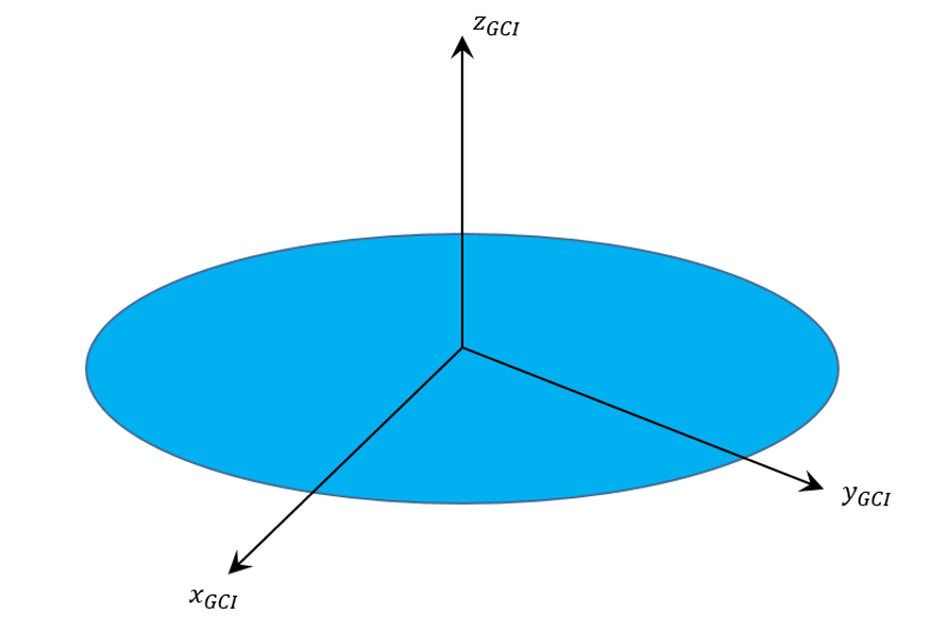
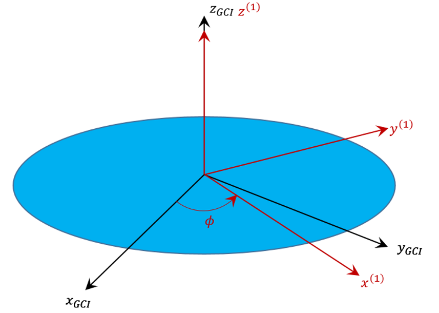
Start with a a known inertial frame here denoted as $$\left\{\hat x_{GCI}, \hat y_{GCI}, \hat z_{GCI} \right\}$$

Step0_Euler_313

and begin by applying the operator $${\mathcal T}_z(\phi)$$ corresponding to a tranformation into a frame rotated by an angle $$\phi$$ about $$\hat z_{GCI}$$.

Step1_Euler_313
The intermediate transformation matrix

\[ {\mathcal A}^{(1)} = \left[ \begin{array}{ccc} \cos \phi & \sin \phi & 0 \\ -\sin \phi & \cos \phi & 0 \\ 0 & 0 & 1 \end{array}\right] \; \]

allows us to read off the basis vectors in the intermediate frame from the rows of $${\mathcal A}^{(1)}$$:

\[ \hat x^{(1)} = \left[ \begin{array}{c} \cos \phi \\ \sin \phi \\ 0 \end{array} \right]_{GCI} \; ,\]

\[ \hat y^{(1)} = \left[ \begin{array}{c} -\sin \phi \\ \cos \phi \\ 0 \end{array} \right]_{GCI} \; ,\]

and

\[ \hat z^{(1)} = \left[ \begin{array}{c} 0 \\ 0 \\ 1 \end{array} \right]_{GCI} \; .\]

The subscript $$GCI$$ reminds us that these vectors are expressed in the inertial frame even though they point along the axes of the intermediate frame.

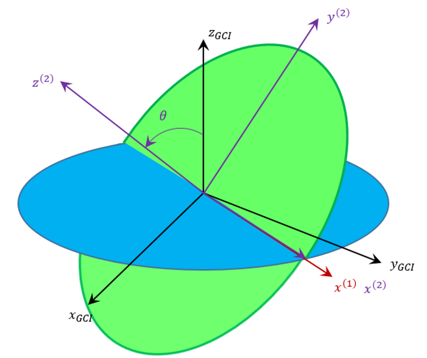
Next apply the operator $${\mathcal T}_x(\theta)$$ corresponding to a tranformation into a frame rotated by an angle $$\theta$$ about $$\hat x ^{(1)}$$.

Step2_Euler_313

The corresponding intermediate transformation matrix

\[ {\mathcal A}^{(2)} = \left[ \begin{array}{ccc} \cos \phi & \sin \phi & 0 \\ – \sin \phi \cos \theta & \cos \phi \cos \theta & \sin \theta \\ \sin \phi \sin \theta & -\cos \phi \sin \theta & \cos \theta \end{array}\right] \; \]

and the basis vectors in this frame are

\[ \hat x^{(2)} = \left[ \begin{array}{c} \cos \phi \\ \sin \phi \\ 0 \end{array} \right]_{GCI} \; ,\]

\[ \hat y^{(2)} = \left[ \begin{array}{c} -\sin \phi \cos \theta \\ \cos \phi \cos \theta \\ \sin \theta \end{array} \right]_{GCI} \; ,\]

and

\[ \hat z^{(2)} = \left[ \begin{array}{c} \sin \phi \cos \theta \\ -\cos \phi \sin \theta \\ \cos \theta \end{array} \right]_{GCI} \; .\]

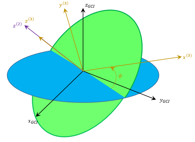
The last step is to appluy $${\mathcal T}_z(\psi)$$ corresponding to a transformation into a frame rotated by an angle $$\psi$$ about $$\hat z^{(2)}$$.

Step3_Euler_313
The final transformation matrix is one of the ingredients we were seeking as is given by

\[ {\mathcal A} = \left[ \begin{array}{ccc} \cos \phi \cos \psi – \sin \phi \sin \psi \cos \theta & \cos \phi \sin \psi \cos \theta + \sin \phi \cos \psi & \sin \psi \sin \theta \\ -\sin \phi \cos \psi \cos \theta – \cos \phi \sin \psi & \cos \phi \cos \psi \cos \theta – \sin \phi \sin \psi & \cos \psi \sin \theta \\ \sin \phi \sin \theta & -\cos \phi \sin \theta & \cos \theta \end{array}\right] \; . \]

Each of the Euler angles has an associated rate $$\left\{\dot \phi, \dot \theta, \dot \psi\right\}$$. The angular velocity in the body frame is related to these rates through

\[ \vec \omega = \vec \omega_{\phi} + \vec \omega_{\theta} + \vec \omega_{\psi} = \dot \phi \hat z_{GCI} + \dot \theta \hat x^{(1)} + \dot \psi \hat z^{(2)} \; .\]

The utility of pulling out the intermediate basis vectors should now be clear.

Carrying out the multiplication gives

\[ \vec \omega = \left[ \begin{array}{c} \dot \theta \cos \phi + \dot \psi \sin \phi \sin \theta \\ \dot \theta \sin \phi – \dot \psi \cos \phi \sin \theta \\ \dot \phi + \psi \cos \theta \end{array} \right]_{GCI} \; ,\]

which is the accepted answer (e.g. problem 19 in Chapter 4 of Goldstein).

The final step is to express this vector’s components in the body frame. This is done by multiplying the column array of inertial components by $${\mathcal A}$$ to get

\[ \vec \omega = \left[ \begin{array}{c} \dot \phi \sin \psi \sin \theta + \dot \theta \cos \psi \\ \dot \phi \cos \psi \sin \theta – \dot \theta \sin \psi \\ \dot \phi \cos \theta + \dot \psi \end{array} \right]_{Body} \; ,\]

which, again, can be favorably compared with Section 4-9 of Golstein (page 179 in the second edition).

The method outlined above is the most straightforward and pedagogically sound one I know. Admittedly, the multiplications and trigonometric simplifications are tedious but with a modern computer algebra system, such as wxMaxima, it can be readily done.

The Speed of a 30 KeV Electron

The world of particle physics abounds with a lot of convenient but specialized jargon that takes some getting used too. This is particularly true in the context of natural units where the speed of light $$c$$ is a fundamnetal yark stick for measuring velocity and mass/energy and where electric charge is measured in units of the charge of an electron. The use of natural units traces back to the roots of the discipline in the studies into electromagnetism. Those practiced in the art specfy energies and masses in units of electron-volts ($$eV$$) and electron-volts per $$c^2$$.

To put things in perspective, note that room temperature $$T \approx 300 k$$ corresponds to an energy content of about $$1/40 eV$$. In contrast, the energy content associated with the mass of an electron is approximately $$511,000 eV$$ or $$511 KeV$$. The key for determining when particle motion can be treated classically versus relativistically is the ratio of kinetic energy to the rest mass energy. At the low energies representative of routine atomic processes ($$< 100 eV$$), the kinetic energy is very small compared with the rest energy and classical methods work well. On the other side are ultra-relativistic energies (such is seen in the LHC) where the kinetic energy is so much larger than the rest energy that the latter can be ignored. The grey area is that stretch inbetween low and ultra-high energy where the ratio ranges from 0.1 to 10 or so. The aim of this note is to look a little at this inbetween zone where the classical description breaks down and gives way to the relativistic one. To set the notation for the relativistic descripion, note that the interval is \[ c^2 dt^2 - dx^2 - dy^2 - dz^2 = c^2 d\tau^2 \] and that coordinate velocities are denoted as $$v^x \equiv \frac{dx}{dt} $$ and so on. Dividing out $$c dt$$ from all terms in the interval gives \[ c^2 dt^2 \left[ 1 - \frac{\vec v^2}{c^2} \right] = c^2 d\tau^2 \; ,\] from which the traditional, relativistic $$\gamma$$ is defined as: \[ \left(\frac{dt}{d\tau}\right)^2 = \frac{1}{\left[1-\vec v^2/c^2\right]} \equiv \gamma^2 \; .\] If a differential movement in spacetime is denoted by \[ dq^{\mu} = \left[\begin{array}{cccc} c dt & dx & dy & dz \end{array} \right] \] and the Minkowski metric \[ \eta_{\mu\nu} = diag(1,-1,-1,-1) \] is used, then the four-velocity is given by \[ u^{\mu} \equiv \frac{d q^{\mu}}{d \tau} = \left[\begin{array}{cccc} c \frac{dt}{d\tau} & \frac{dx}{d\tau} & \frac{dy}{d\tau} & \frac{dz}{d\tau} \end{array} \right] \; .\] The chain rule proves particularly helpful, allowing the coordinate time $$t$$ to be used in place of the proper time $$\tau$$:0 \[ u^{\mu} = \frac{dt}{d\tau}\left[\begin{array}{cccc} c & \frac{dx}{d\tau} \frac{d\tau}{dt}& \frac{dy}{d\tau}\frac{d\tau}{dt} & \frac{dz}{d\tau}\frac{d\tau}{dt} \end{array} \right] \; .\] Factoring out the $$\gamma$$ gives a compact form for the four-velocity of \[ u^{\mu} = \gamma \left[\begin{array}{cc}c & \vec v \end{array} \right] \; .\] The four-momentum is defined as \[ p^{\mu} = m u^{\mu} = m \gamma \left[\begin{array}{cc}c & \vec v \end{array} \right] \; . \] The normalization of the four-momentum is of particular physical interest. It is defined as: \[ p^{\mu} p_{\mu} = m^2 \gamma^2 \left[\begin{array}{cc}c & \vec v \end{array} \right] \left[\begin{array}{cccc}1 & 0 & 0 & 0 \\ 0 & -1 & 0 & 0 \\ 0 & 0 & -1 & 0 \\ 0 & 0 & 0 & -1 \end{array} \right] \left[\begin{array}{c}c \\ \vec v \end{array} \right] \; ,\] which simplifies to \[ p^{\mu}p_{\mu} = m^2 \gamma^2 (c^2 - \vec v^2) = m^2 \gamma^2 c^2 \left[1-\vec v^2/c^2\right] = m^2 c^2 \; . \] The zeroth component, \[ p^0 = m c \gamma = \frac{m c}{\sqrt{1-\frac{\vec v^2}{c^2} }} \; ,\] is related to the total energy by the equation \[ E = c p^0 = mc^2 \gamma = \frac{RE}{\sqrt{1 - \frac{\vec v^2}{c^2}}} \; .\] This last relation is cornerstone for looking at the cross-over from classical to relativistic descriptions. The approach will be to compute the coordinate velocity both ways and to compare the relative error made in the classical expression. Two different scenarios will be explored. The first is the usual one where we know the kinetic energy of the particle, having accelerated it through fixed potential difference. The second, and far less common scenario, is where we know the relativistic momentum of the particle after a collision. Scenario 1: Measure the kinetic energy By its thermodynamic definition, energy is additive and the total energy of a particle is given by the sum \[ E = K + RE \] of its kinetic energy $$K$$ and rest energy $$RE = m c^2$$. Recasting the definition of energy given above in terms rest energy gives \[ E = \frac{RE}{\sqrt{1 - \frac{\vec v^2}{c^2}}} \; .\] Equating the two expressions gives \[ \frac{RE}{\sqrt{1 - \frac{\vec v^2}{c^2}}} = K + Re \; ,\] which can be simplified to \[ K = (\gamma - 1) RE \; .\] Next define the ratio of kinetic and rest energies as \[ b = \frac{K}{RE} \; .\] Using this definition leads to the identity \[ b + 1 = \gamma \] and the subsequent expression for the coordinate velocity \[ v = c \sqrt{ 1 + \frac{1}{(1+b)^2} } \; \] For a $$K = 30 \; KeV$$ electron, with rest energy $$RE = 510.839 \; KeV$$, the resulting coordinate velocity (really speed) is \[ v = 98458.806 \; km/s \; .\] The classical method, expressed via the usual relation $$K = 1/2 m v^2$$, yields \[ v_{classical} = \sqrt{\frac{2 K}{m_e}} \] or, numerically, \[ v_{classical} = 102743.45 \; km/s \; ,\] corresponding to a relative error of $$\epsilon_1 = 0.0435171$$. While not a gross error, using the classical expression results in a non-negligible difference. Scenario 2: Measure the relativistic momentum If instead of knowing the kinetic energy, suppose we know the spatial portion of the relativistic four-momentum $${\mathcal P}^2 = \vec p^2 c^2$$. The normaliztion of the four-momentum means that \[ E^2 = m^2 c^2 + p^2 c^2 \equiv RE^2 + {\mathcal P}^2 \; .\] Defining the ratio \[ d = \frac{{\mathcal P}}{RE} \] and factoring and taking the square root gives \[ E = RE \sqrt{1 + d^2} \; .\] Combining with the formula for $$E$$ in terms of $$\gamma$$ allows us to determine \[ v = c\sqrt{1-\frac{1}{1+d^2}} = c \sqrt{\frac{d^2}{1+d^2}} \; .\] If we suppose that the energy associated with $${\mathcal P} = 30 KeV$$ then the resulting speed is \[ v = 17575.59 \; km/s \] whereas the classical expression is \[ v_{classical} = 17598.29 \; km/s \; .\] The relative error is $$\epsilon_2 = 0.00192$$; substantially smaller than the case reflecting the fact that the speed is so much smaller (almost a factor of 6 smaller). It is interesting to note that, in both cases, the classical expression overestimates the speed. This is consistent with the notion that the classical theory has no fundamental speed limit like relativity but it this is only a conjecture at this point.

Scattering: Part 5 – Odds and Ends

This week’s column is the last installment of a long and detailed look at scattering in classical mechanics. Up to this point specific potentials ($$1/r$$ and $$e^{-r/R}/r$$) have been used and the specific relationship between the impact parameter $$b$$ and the scattering angle $$\theta$$ has been derived either analytically ($$1/r$$) or numerically ($$1/r$$ and $$e^{-r/R}/r$$). This week, I am going to talk about scattering in general and clear up a few loose ends, including a close look at the traditional definition of scattering cross section.

One might argue that the omission of the scattering cross section in these previous studies has been glaring. But as I’ve argued elsewhere, I prefer the definition of the scattering cross section in terms of relative probability and I believe that the insistence on deriving ‘an effective area’ to be a hold over from the pre-quantum days when Rutherford scattering was a new technique and its results were revolutionary. While it is true that scattering results in particle physics still are expressed in barns (or some faction therein), their interpretation is clearly couched in terms of fractions of outcome events compared to all the possible events. In addition, in all my professional work in planetary flybys, I’ve never seen anyone actually calculate a scattering cross section. Rather everything is expressed in terms of impact parameter $$b$$ (from which the b-plane derives its name) and the bend or scattering angle. Even when performing Monte Carlo analysis of flyby control and navigation, no one suggests using cross section. Nonetheless, a really thorough treatment would be incomplete without some discussion.

My treatment here closely follows the arguments found in Chapter 6 of Introduction to Elementary Particles, 2nd edition by David Griffiths. Griffiths doesn’t present anything new, per se, but he is careful in his pedagogy – particularly his ‘derivation’ of $$\frac{d\sigma}{d\Omega}$$ and it is worth extending his approach.

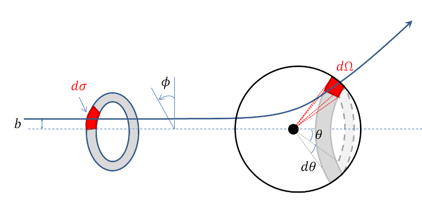
The generic scattering scenario is shown in the figure below.

Scattering Cross Section

In it, we imagine a uniform and collimated beam of particles streaming towards a scattering center. Focus on one slice through the beam at a point where the particles are still far from the scatterer. Narrow the focus again to those particles in an annular ring with inner radius $$b$$ and outer radius $$b+db$$, denoted by the gray shading. And, finally, narrow the focus one more time to particles in that ring that reside in the sector between azimuth angles $$\phi$$ and $$\phi + d\phi$$. This sector, of area $$d\sigma$$, is denoted by the red shading. As the annular ring propagates towards the scatter, the individual particles begin to be deflected and eventually, when sufficiently long time has passed, the ring will have become distorted into the gray annulus on the sphere surrounding the scatter. In particular, the original red sector has been transformed into a region of solid angle $$d\Omega$$ on the sphere. The (differential) scattering cross section relates the two through

\[ d \sigma = D(\theta,\phi) d \Omega \; .\]

The introduction of $$D(\theta, \phi)$$ by Griffiths is a nice pedagogical touch as it divorces the concept from the stupid notation $$\frac{d\sigma}{d\theta}$$ which is neither explanatory nor actually a derivative in the rigorous sense. By dimensional arguments, $$D(\theta,\phi)$$ must have units of area, a point on which I will elaborate more below.

The area of the sector is

\[ d\sigma = |b \, db \, d\phi| \]

and the solid angle is

\[ d\Omega = |\sin \theta \, d\theta \, d\phi| \; .\]

Note that since area and solid angle are intrinsically positive quantities, whereas $$db$$, $$d\phi$$, and $$d\theta$$ can have any sign, absolute value must be used.

Substituting these relations in and solving for $$D(\theta,\phi)$$ yields

\[ D(\theta,\phi) = \frac{d\sigma}{d\theta} = \frac{|b \, db \, d\phi|}{|\sin \theta \, d\theta \, d\phi|} = \frac{b}{\sin \theta}\left|\frac{db}{d\theta}\right| \; , \]

where $$b$$ and $$\sin\theta$$ can be taken out of the absolute values since they are always positive (since $$b$$ is a radius and $$\sin\theta \ge 0 $$ for $$\theta \in [0,\pi]$$).

So having the relationship between the impact parameter $$b$$ and the scattering angle $$\theta$$ is essentially the same as having the scattering cross section.

For the case of Coloumb scattering, the relationship (as derived in Part 3) is

\[ \cot^2 \left(\frac{\theta}{2}\right) = \frac{4 E^2 b^2}{\alpha^2} \; .\]

To get the scattering cross section, first solve for $$b$$ in terms of $$\theta$$ (note that since we will be taking an absolute value, the sign from the square root doesn’t matter)

\[ b = \frac{\alpha}{2 E} \cot \left( \frac{\theta}{2} \right) \]

and then take the derivative

\[ \left| \frac{db}{d\theta} \right| = \frac{\alpha}{4 E} \csc^2 \left( \frac{\theta}{2} \right) \; . \]

A clever rewriting of $$\sin \theta = 2 \sin\left(\frac{\theta}{2}\right) \cos\left(\frac{\theta}{2}\right)$$ gives

\[ D(\theta,\phi) = \frac{\frac{\alpha}{2E} \frac{\cos\left(\frac{\theta}{2}\right)}{\sin\left(\frac{\theta}{2}\right)}}{2 \sin\left(\frac{\theta}{2}\right) \cos\left(\frac{\theta}{2}\right)} \cdot \frac{\alpha}{4 E} \frac{1}{\sin^2\left(\frac{\theta}{2}\right)} = \; \; \; \frac{1}{4} \left(\frac{\alpha}{2E}\right)^2 \csc^4 \left( \frac{\theta}{2} \right) \; ,\]

which is the famous Rutherford result.

Physically, from the defining equation, $$D(\theta,\phi) d\Omega$$ is the area of the image of the incoming red sector under the action of the scattering. It is often expressed as

\[ D(\theta,\phi) d\Omega = \frac{\textrm{# of particles per unit time scattered into } d \Omega}{\textrm{incident intensity}} \; . \]

To see why, suppose that the incident intensity $$I_0$$ is given by

\[ I_0 = \frac{N}{A \delta t} \; ,\]

where $$N$$ is the number of particles in the beam, $$A$$ is the cross sectional area of the beam, and $$\delta t$$ is some measure of unit time. Let $$N_{d\Omega}$$ be the number of particles scattered in solid angle $$d\Omega$$. The unit of time cancels leaving

\[ D(\theta,\phi) d\Omega = A \frac{N_{d\Omega}}{N} \; ; \]

so, like in the Monte Carlo case discussed earlier, the area of the image can be inferred by counting how many particles end up in it relative to the number of particles sent in and multiplying the initial area of the beam by this scale factor. For those needing a bit more convincing, realize that the number of scattered particles $$N_{d\Omega}$$ is equal to the number of particles in the original red sector (this is a classical setting to local neighborhoods propagate into local neighborhoods). The number of particles in the original red sector is the fraction of cross sectional area it consumes times the total number or

\[ N_{d\Omega} = N_{d\sigma} = N \frac{d\sigma}{A} \; ,\]

which when substituted into the previous equation gives $$D(\theta,\phi) d \Omega = d\sigma$$ as desired. The experimentalist is likely to massage these last relationship into a pithier statement: $$D(\theta,\phi) d\Omega = N_{d\Omega} / I_0$$ (the cross section equals the particles counted divided by the beam intensity).

Nowhere in any of the above discussion is there an interpretation that says that $$D(\theta,\phi) d\Omega$$ is somehow the size of the scatterer. In fact, if one defines, the size of the scatter as

\[ S = \int d\Omega D(\theta,\phi) \]

then one is baffled by the result that, for Coloumb scattering, the size of the scatterer is infinite. Bigger than the experiment, bigger than the universe, and certainly so big as to thwart every assumption we have about incoming and outgoing unbound states. This is the heart of my objection to that interpretation.

So from where does such an interpretation spring? Well, in one particular case – and only in this case – does it make some kind of sense. For scattering from a hard sphere

hard sphere scattering

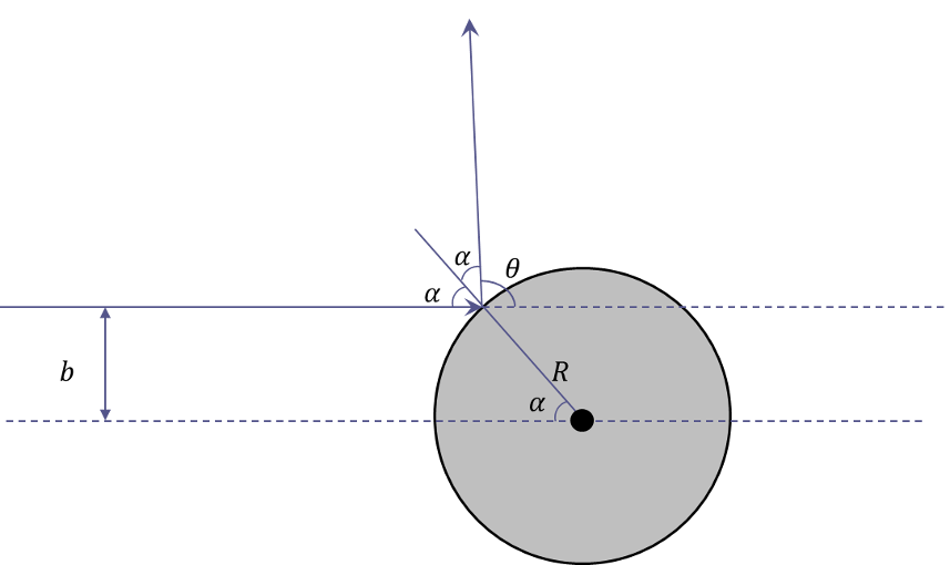
the relationship between the impact parameter and the scattering angle (which can be read off from the above geometry) is

\[ b = R \cos\left(\frac{\theta}{2}\right) \; . \]

The derivative, which is very easy to compute, is

\[ \frac{db}{d\theta} = -\frac{R}{2} \sin\left(\frac{\theta}{2}\right) \; \]

and

\[ D(\theta,\phi) = \frac{R^2}{4} \; .\]

Integrating this expression over the entire solid angle gives

\[ \int d\Omega D(\theta,\phi) = \pi R^2 \; .\]

Certainly interesting and encouraging, but totally misleading, since the ‘potential’ for hard sphere scattering has compact support, a situation that most potentials of interest fail to possess.

Scattering: Part 4 – Debye Scattering

In last week’s column, the relationship between the impact parameter and the scattering angle for a $$1/r$$ potential was examined in some detail for both attractive and repulsive scattering. The excellent agreement between theory and the numerical simulations was evident in how well the energy, angular momentum, and eccentricity vector were conserved and in how accurately the observed scattering angle matched the predicted functional form as a function of impact parameter.

This week, the picture changes somewhat as the $$e^{-r}/r$$ potential replaces the $$1/r$$ potential. In addition, the coupling constant $$\alpha$$ will always be negative so that repulsive scattering results in both cases for easy comparison. For convenience, the $$1/r$$ case will be referred to as Coulomb scattering. Although a genuine argument can be made for Rutherford scattering as the proper name, based on the his historic experiments, I use Coulomb since the resulting force comes from Coulomb’s law.

The new force law is dubbed Debye since it is functionally identical to the force that results from Debye shielding in a plasma. The full form of the potential is

\[ \frac{\alpha e^{-r/R}}{r} \; , \]

where $$R$$ sets the scale length of the potential. The corresponding Debye equation of motion is

\[ \ddot {\vec r} + \frac{\alpha (R+r) e^{-r/R} }{R r^3} \vec r = 0 \; .\]

Since the Debye force is central and time-invariant, angular momentum and energy are conserved. The eccentricity vector, which is properly a quantity only for conic sections, is not used in the Debye case. Most likely there isn’t an additional conserved quantity that is it’s analog for Debye scattering. This conclusion is based on Betrand’s Theorem, which says that only $$1/r$$ and $$r^2$$ potentials have bound orbits which close (i.e. have a conserved eccentricity vector). Since the derivation that gave the conservation of $$\vec e$$ in the Coulomb case did not depend on the orbits being bound, the obvious conclusion is that an additional conserved quantity on par with the eccentricity vector doesn’t exist for $$e^{-r}/r$$ potentials. In any event, it was only used to get the radial equation and then to subsequently derive an analytical expression that relates the scattering angle $$\theta$$ to the impact parameter $$b$$. Numerical simulations will serve just as well in this case.

Before simulating the scattering, it is helpful to have an expectation as to the general qualitative results. The figure below shows a comparison between the Coloumb and Debye potentials near the scattering center. Note that three separate values of $$R = 2, 1, 1/2$$ are displayed.

Debye and 1_r potentials

In all cases, the Debye potential is below the Coulomb potential, sometimes substantially so. As $$R$$ increases, the Debye ppotential uniformly approaches the Coulomb potential and in the limit as $$R \rightarrow \infty$$, they become the same.

As before, all the numeric simulation were performed using numpy, scipy, and matplotlib within the Jupyter framework. The right-hand-side (RHS) of the equations of motion was computed from

def Debye(state,t,params):
    #unpack the state
    x     = state[0]
    y     = state[1]
    z     = state[2]
    vx    = state[3]
    vy    = state[4]
    vz    = state[5]
    
    #unpack params
    alpha = params['alpha']
    R     = params['R']
    
    #define helpers
    r     = sp.sqrt(x**2 + y**2 + z**2)
    q     = alpha*(r+R)*sp.exp(-r/R)/r**3/R
    
    #state derive
    ds = [vx, vy, vz, -q*x, -q*y, -q*z]
    return ds

Note the implicit understanding that the python dictionary params is now carrying the values of two simulation constants: $$\alpha$$ and $$R$$.

Since the force was derived from a potential, the form of the conserved energy for Debye scattering is

\[ E = \frac{1}{2} v^2 – \frac{\alpha e^{-r/R}}{r} \; .\]

As a check on the accuracy of the simulation, a specific scattering case was examined in detail for both the Debye and Coulomb cases. The initial conditions were

\[ \bar S = \left[ \begin{array}{c} -30 \\ 0.1 \\ 0 \\ 2.25 \\ 0 \\ 0 \end{array} \right] \; .\]

The results for the conserved energy and angular momentum, shown in the figure below, indicate excellent behavior from the numerical simulation.

Conserved_Quantities_Debye

For comparison, the resulting conservation accuracy in the Coloumb case, shown below, is essentially the same.

Conserved_Quantities_Coulomb

Based on the qualitative analysis of the potentials, we expect to see that Debye scattering gets closer to the scattering center and is deflected less than Coulomb scattering, all other things remaining the same. This is exactly what is observed.

Scattering_comparison

With these initial validations done, the final step is to scan over a variety of impact parameters and then to compare the behavior of the scattering angle in the two cases. The same scan_impact_param function was used as in the last post with one modification. The calling sequence was modified to take an additional argument called model, which is a function pointer to the desired RHS of the equation of motion.

def scan_impact_param(b_range,s0,params,model):
    theta              = b_range[:]*0.0
    counter            = 0
    for b in b_range:
        timespan       = np.arange(0,20,0.001)
        s0[1]          = b
        soln           = ode(model,s0,timespan,args=(params,),rtol=1e-8,atol=1e-10)
        theta[counter] = scattering_angle(soln)
        counter        = counter + 1
    return theta


The resulting scattering plot shows, as expected, that the Debye potential allows the scattered particle closer access to the scattering center for a given scattering angle than does the Coulomb potential.

Scattering_Angle_v_b

Next week, I’ll tidy up some odds and ends and close out this revisit of classical scattering.

Scattering: Part 3 – Cross Section

The last post presented the basic methods for numerically integrating a scattering trajectory in a $$1/r$$ potential and demonstrated the excellent agreement between the theoretically-derived conserved quantities and the numerically generated ephemerides. In addition, the point of closest approach predicted from the radial equation agreed to a high degree of precision with what was seen in the integrated trajectories.

This installment extends these techniques to an ensemble of trajectories and, in doing so, allows for the same kind of validation of the scattering cross section predicted by the theory with those obtained from the simulated trajectories.

The theoretical results will be obtained from an careful analysis of the radial equation and the adoption of the usual definitions that related the impact parameter $$b$$ with the outgoing scattered angle $$\theta$$. The simulation results come from routines that scan over values of the impact parameter, produce the corresponding simulated trajectory, and then determine the scattering angle. As in last week’s post, all the numerical modeling is done using Python 2.7 with numpy, scipy, and matplotlib.

The figure below shows an ensemble of scattering trajectories, all having the same energy, that differ only in the perpendicular distance, called the impact parameter $$b$$, from the scattering center.

ensemble_scattering

The smaller values of $$b$$ have the much larger deflection and the variation as the impact parameter is changed clearly not linear. The scattering geometry for an arbitrary trajectory is shown here

Definition of the scattering angle


The scattering angle $$\theta$$, obviously a function of impact parameter $$b$$, is what we are looking to obtain. Three separate pieces are need to derive a relationship between the scattering angle and the impact parameter:

  1. relate the impact parameter to the angular momentum and energy
  2. relate the eccentricity to the angular momentum and energy
  3. relate the scattering angle to the eccentricity

The first and third relationships are relatively easy but the second requires some work. Let’s take them in order.

Impact Parameter, Angular Momentum, and Energy

Note that far from the scattering center ($$r \rightarrow \infty$$), the incoming velocity $$\vec v_i$$ is perpendicular to the perpendicular distance of the incoming asymptote from the scattering center. This latter term has a magnitude $$b$$ and thus the magnitude of the angular momentum is

\[ L = b v_i \; . \]

At an infinite distance from the scattering center, the potential energy contributes nothing, and the energy is given by

\[ E = \frac{1}{2} v_i^2 \; .\]

Eccentricity, Angular Momentum, and Energy

Relating impact parameter to the angular momentum and the energy is best done by working with a periapis. While there is way to handle both repulsive and attractive scattering on the same footing, it is easier to take them one at a time. Nonetheless, the formula that obtains in both cases is the same.

For repulsive scattering, the radius and the speed at periapis become

\[ r_p = \frac{p}{e-1} = -\frac{L^2}{\alpha (e-1) } \; ,\]

(since $$p=-L^2/\alpha$$), and

\[ v_p = \frac{L}{r_p} = -\frac{\alpha}{L}(e-1) \; .\]

Plugging both of these into the energy gives the expression

\[ E = \frac{1}{2} \frac{\alpha^2}{L^2} (e-1)^2 – \frac{\alpha}{-L^2/\alpha} (e-1) \; .\]

Expanding and simplifying results in

\[ \frac{2 E L^2}{\alpha^2} = e^2 – 1 \]

or, as it is more usually expressed

\[ e = \sqrt{1 + \frac{2 E L^2}{\alpha^2} } \; .\]

Following similar lines, the radius and speed at periapsis for attractive scattering are

\[ r_p = \frac{p}{1+e} = \frac{L^2}{ \alpha (1+e) } \; , \]

(since $$p = L^2/\alpha$$), and

\[ v_p = \frac{\alpha}{L} (1+e) \; .\]

Again plugging these into the energy equation is the next step, which gives

\[ E = \frac{1}{2} \frac{\alpha^2}{L^2} (1+e)^2 – \frac{\alpha^2}{L^2}(1+e) \; .\]

Expanding and simplifying results in exactly the same expression as above. This seemingly coincidental good fortune is a consequence of the underlying conic section properties of these hyperbolic orbit.

Scattering angle and eccentricity

The condition for starting far from the scattering center such that $$r \rightarrow \infty$$ requires that the denominator of the radial equation tend to zero. Taking that limit yields

\[ e \cos \gamma – 1 = 0 \; ,\]

for repulsive scattering, and

\[ 1 + e \cos \gamma = 0 \; , \]

for attractive scattering. The angle $$2 \gamma$$ is often referred to as the bend angle for attractive scattering (for example in analyzing planetary flybys). The relationship between the half-bend angle $$\gamma$$ and the scattering angle $$\theta$$ is

\[ 2 \gamma + \theta = \pi \]

as can be determined, by inspection, from the scattering geometry figure above.

For repulsive scattering,

\[ \cos \gamma = \cos \left(\frac{\pi}{2} – \frac{\theta}{2} \right) = \sin\left(\frac{\theta}{2} \right) = \frac{1}{e} \;. \]

For attractive scattering,

\[ \cos \gamma = \cos \left( \frac{\pi}{2} – \frac{\theta}{2} \right) = \sin \left(\frac{\theta}{2}\right) = -\frac{1}{e} \; .\]

Now we are in position to combine all these ingredients together to get the desired relationship.

Substituting the initial conditions $$E = \frac{1}{2} v_i^2$$ and $$L = b v_i$$ into the eccentricity-angular-momentum-energy relation gives

\[ e^2 = 1 + \frac{2 E b^2 v_i^2}{\alpha^2} = 1+ \frac{4 E b^2 \left( \frac{1}{2} v_i^2\right)}{\alpha^2} = 1 + \frac{4 E^2 b^2}{\alpha^2} \; . \]

Eliminating $$e$$ in favor of the scattering angle $$\theta$$ yields

\[ \frac{1}{\sin^2\left(\frac{\theta}{2}\right)} = 1 + \frac{4 E^2 b^2}{\alpha^2} \; ,\]

where the sign difference between the two types of scattering is now lost since the key relationship involves $$e^2$$.

Using standard trigonometric relations yields the traditional expression

\[ \cot^2\left(\frac{\theta}{2}\right) = \frac{4 E^2 b^2}{\alpha^2} \; .\]

In order to test this expression, two new functions were added to the Python suite of tools. The first is function that takes the ephemeris and calculates the approximate scattering angle by taking the dot product between the first and last velocities. Note the careful avoidance of calling them either the initial or final velocities as there is no practical way to start or finish an infinite distance away.

def scattering_angle(soln):
    vi     = soln[0,3:6]
    vf     = soln[max(soln.shape)-1,3:6]
    vi_mag = sp.sqrt( vi[0]**2 + vi[1]**2 + vi[2]**2 )
    vf_mag = sp.sqrt( vf[0]**2 + vf[1]**2 + vi[2]**2 )
    vdot   = vi[0]*vf[0] + vi[1]*vf[1] + vi[2]*vf[2]
    theta = sp.arccos(vdot/vi_mag/vf_mag)
    return theta

The second function scans over a range of impact parameters and returns the scattering angle for each value.

def scan_impact_param(b_range,s0,params):
    theta              = b_range[:]*0.0
    counter            = 0
    for b in b_range:
        timespan       = np.arange(0,60*200,30)
        s0[1]          = b
        soln           = ode(TwoBody,s0,timespan,args=(params,),rtol=1e-8,atol=1e-10)
        theta[counter] = scattering_angle(soln)
        counter        = counter + 1
    return theta

Taken together, they comprise the ‘experimental’ measurements for these simulations.

Running these for repulsive scattering gives excellent agreement between theory (red line) and experiment (blue dots).

repulsive_scattering_cross_section

Likewise, similarly excellent agreement is obtained between theory (red line) and experiment (blue dots) for attractive scattering.

attractive_scattering_cross_section

Note that the difference between the two plots is attributable to the fact that the same initial conditions (except for the value of $$b$$) were used in both simulations. This was done for convenience. In sign difference in the potential results in higher energy scattering in the repulsive case compared to the attractive and this is why the attractive scattering is slightly more pronounced.

Now that we are sure that our relationship between $$b$$ and $$\theta$$ is correct, we can derive the differential scattering cross section. This will be covered in detail in next week’s installment.