
This week I’ve decided to take a look at an innocent-looking experiment from elementary mechanics that is a lot more subtle than I think most people realize. I justify this assertion from the many incorrect statements concerning this experiment that can be found in the internet and from the general fuzziness in thinking that both myself and my colleagues had when discussing this. The experiment consists of taking some handy items and rolling them down an inclined plane.
The genesis of this experiment was a high school physics experiment on rotational dynamics that my son was tasked to perform recently. I’ve always enjoyed rotational dynamics and, after we had discussed performing this particular experiment, I went to Home Depot and purchased some wood and metal rods and some metal tubes of various radii and lengths. I dutifully brought the booty home, pulled out a miter box and the appropriate saws, and cut the pieces to a common length. Of course, the length of a cylinder rolling down an inclined plane can’t possibly matter – reflect for a moment on whether one cylinder of length $$L$$ will go down the plane differently than two cylinders, side-by-side, of lengths $$L/2$$ – but I wanted to keep things simple. However, when we performed the experiment, the results were not what I expected. My son and I sat down and worked through the free-body diagram and reached an amazing realization that I will share.
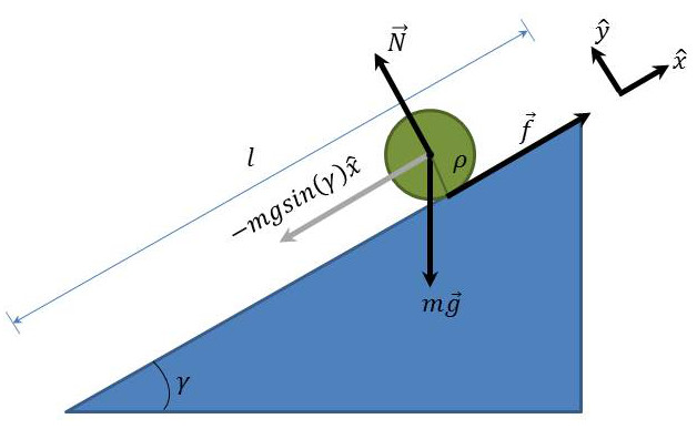
The figure below shows the free-body diagram for any object with a circular cross section rolling down an inclined plane. The forces on the object are: the force due to gravity $$m \vec g$$ acting on the center of mass, the normal force $$\vec N$$ exerted on the object by the plane, and the frictional force $$f$$. These are shown as black arrows in the diagram. The coordinate system $$\{ \hat x, \hat y\}$$ is aligned with the inclined plane so that only the gravitational force needs to be resolved into components, the only relevant one being $$-m g \sin( \gamma ) \hat x$$, shown in gray.
Application of Newton’s second law gives
\[ – m a \hat x = – m g \sin ( \gamma ) \hat x + f \hat x \]
for the acceleration $$a$$ of the object down the inclined plane.
Since we’ve stipulated that the object will roll down the inclined plane, there is a natural relationship between the linear distance travelled $$s$$ and the amount the object has rotated $$\theta$$ that is given by
\[ s = \rho \, \theta \; , \]
where $$\rho$$ is the radius.
Taking the first and second derivatives of this relationship yields
\[ s = \rho \, \theta \implies \; v = \rho \, \omega \implies \; a = \rho \, \alpha \]
or
\[ \alpha = \frac{a}{\rho} \; .\]
Now, the torque needed to rotate the object so that it rolls down the plane is provided by the frictional force $$\vec f$$, which always acts tangentially so that
\[ \vec \tau = \vec r \times \vec f \implies \; \tau = \rho f \; .\]
The amount of angular acceleration $$\alpha$$ delivered by the torque is given by
\[ \tau = I \alpha \; ,\]
where $$I$$ is the moment of inertia of the object. There will be a lot more said about $$I$$ later on.
Equating these two expression for $$\tau$$ gives
\[ f = \frac{I \alpha}{\rho} \; .\]
Finally, substituting in the expression for $$\alpha$$ in terms of $$a$$ gives
\[ f = \frac{I a}{\rho^2} \; .\]
At this point, the magnitude of the frictional force has been expressed in terms of the linear acceleration of the object down the plane and in terms of the object’s properties, and so the frictional force can be eliminated from the application of Newton’s second law, leaving
\[ -m a = -m g \sin( \gamma ) + \frac{I a}{\rho^2} \; .\]
Note that the sign of the last term must be positive since $$\vec f$$ is in the positive $$\hat x$$ direction.
Now solve for the acceleration to get
\[ a = \frac{ g \sin( \gamma ) }{1 + \frac{I}{m \rho^2}} \; .\]
The final step is to relate the acceleration to the time it takes the object to descend the inclined plane under the constant acceleration determined above since that is the most convenient observable. Using the standard kinematic formula for motion under the influence of a constant acceleration and assuming the object starts at the top of the inclined plane at rest, the time it takes to reach the bottom, a distance $$L$$ from the top is
\[ t = \sqrt{ \frac{2 L}{ g \sin( \gamma ) } \left( 1 + \frac{I}{m \rho^2} \right) } \; .\]
A cursory glance at this formula would tend to coax one into the idea that an object with a larger moment of inertia would take a longer time descending the inclined plane. And this expectation seems to be widespread. For example, the article on calculating moments of inertia in Wikipedia has an animation showing a solid sphere, a solid cylinder, a spherical shell, and a cylindrical ring, all starting from rest at the top of an inclined plane. Each of these objects is released at the same time and they reach the bottom in the order listed in the previous sentence. The result of the animation is correct, but the caption is misleading. The author cites as reason that the resulting order depends on their moments of inertia. This is not true – the order depends only on the geometric distribution and has nothing whatever to do with the amount of matter contained in the object or with the size of the object.
To get a feel for why this result holds, consider a steel solid cylinder $$5 \, cm$$ long and $$0.5 \, cm$$ in radius. Assuming the density of steel to be $$8 \, g/cm^3$$, the mass of the cylinder is $$m = 31.4 \, g$$ and the moment of inertia is $$I = 3.9 \, g-cm^2$$. Now consider a steel tube of the same length with an inner radius $$\rho_1 = 0.4 \, cm$$ and an outer radius of $$\rho_2 = 0.5 \, cm$$. The mass and moment of inertia for the tube are $$m = 11.3 \, g$$ and $$I = 0.51 \, g-cm^2$$, respectively. The times for the two objects to descend a 1-meter long plane inclined at $$10 \, deg$$ are: $$t_{cylinder} = 1.33 \, s$$ and $$t_{tube} = 1.18 \, s$$. So, even though the cylinder has the greater mass (by a factor of 2.8) and moment of inertia (by a factor of 7.7), requiring a greater torque to set it rolling, it reaches the bottom first.
The key to understanding this result is to note that the moment of inertia enters in the equation in direct ratio to the $$m \rho^2$$. From dimensional grounds, the moment of inertia of any object rolling down the inclined plane must be
\[ I = k \, m \rho^2 \; , \]
where $$k$$ depends on the distribution of the matter but not on the amount or density. For common shapes, the moments of inertia (and correspondingly the values of $$k$$) are:
| Shape | \[ I \] |
|---|---|
| Solid Sphere | \[ \frac{2}{5} m \rho^2 \] |
| Solid Cylinder | \[ \frac{1}{2} m \rho^2 \] |
| Spherical Shell | \[ \frac{2}{3} m \rho^2 \] |
| Cylindrical Ring | \[ m \rho^2 \] |
which explains the order shown in the Wikipedia article: $$k_{Solid Sphere} < k_{Solid Cylinder} < k_{Spherical Shell} < k_{Cylindrical Ring}$$. As an extreme case, consider a concrete pillar $$5 \, m$$ in radius with a mass of several metric tons and an acrylic tube with an outer radius of $$0.5 \, cm$$ and a thickness of $$0.1 \, cm$$ with a mass of a few grams. Set these objects at the top of the same inclined plane and allow them to descend from rest at the same time. The concrete pillar will reach the bottom first despite the fact that its moment of inertia dwarfs that of the plastic tube by maybe 15-20 orders of magnitude. Amazing, isn't it?